 Skip to content

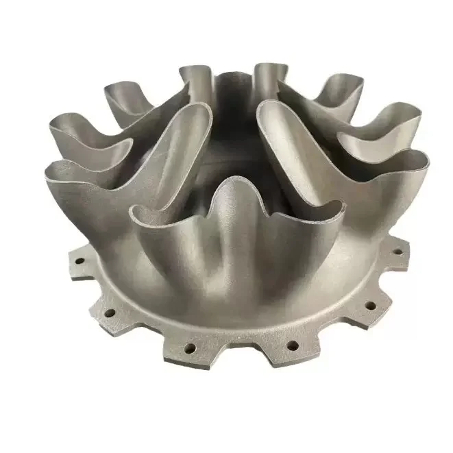
Comparison with Casting
Microstructure Advantage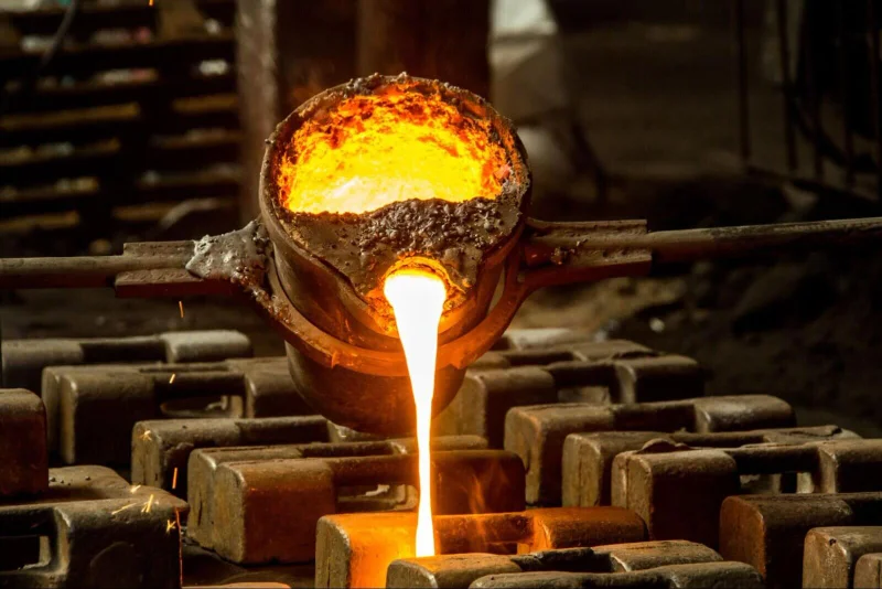
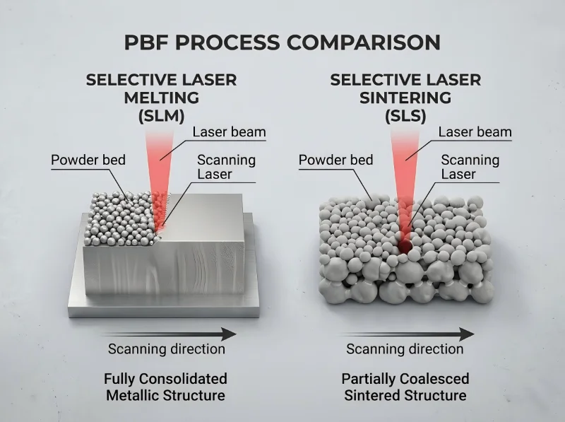
SLM parts exhibit a finer microstructure than cast parts due to rapid cooling rates associated with the laser process. This often results in higher Yield Strength and Ultimate Tensile Strength (UTS) compared to their cast counterparts. SLM eliminates the porosity defects common in casting.
Comparison with Forging
Grain Alignment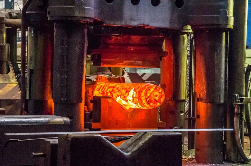
While forging aligns the grain structure of the metal for maximum strength, SLM parts are generally comparable to annealed wrought materials. With proper heat treatment, SLM parts can achieve equivalent or superior performance.
Why SLM Parts Excel in Strength
Fine Microstructure
Rapid cooling creates smaller, more uniform grains
Zero Porosity
Unlike casting, no shrinkage cavities or gas pores
Density Optimization
99.9% density ensures maximum material utilization
Controlled Cooling
Predictable material properties across entire part
Post-Processing
Heat treatment further enhances mechanical properties
Addressing Anisotropy & Achieving Isotropic Strength
Key to noting is Anisotropy. "As-printed" SLM parts may be slightly weaker in the Z-axis (vertical direction) due to the layer-by-layer nature. However, via post-process Heat Treatment and Stress Relieving, the grain structure recrystallizes, making the part isotropic (equally strong in all directions).
Our SLM parts are manufactured and heat-treated to meet the following international standards:
Titanium alloys
Tensile testing
Implantable materials
Pyrometry standards
Metallic materials testing
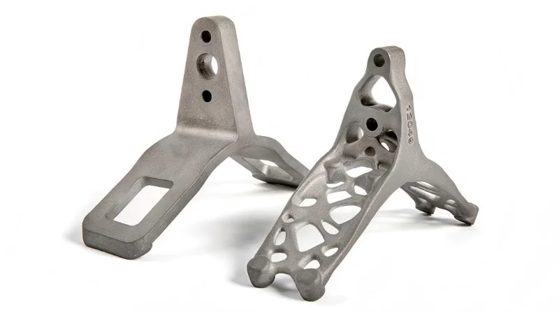
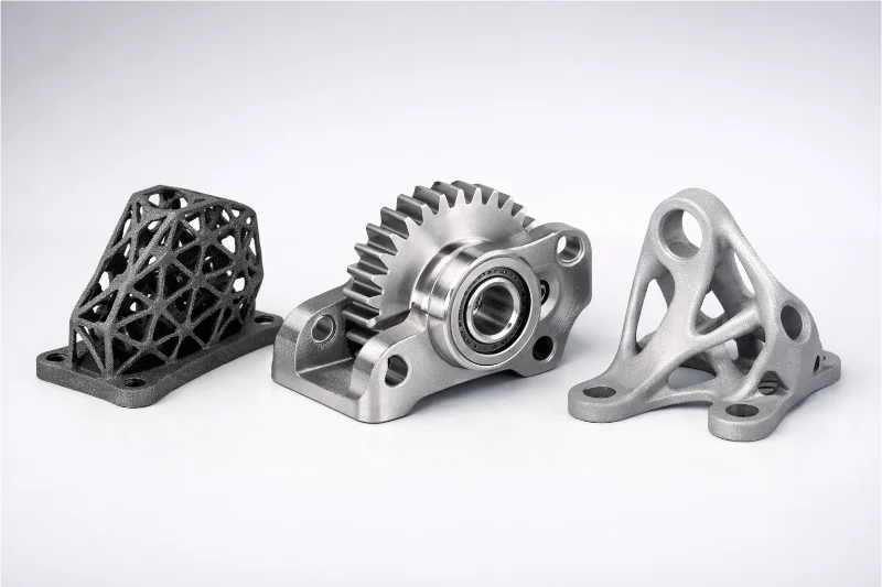
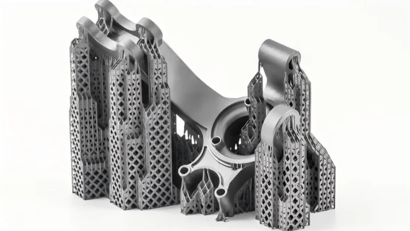
Topology Optimization
Engineers can use simulation software to determine exactly where material is needed to support a load. SLM can print these organic, bionic shapes that remove excess weight without sacrificing strength. This is crucial for aerospace weight reduction.
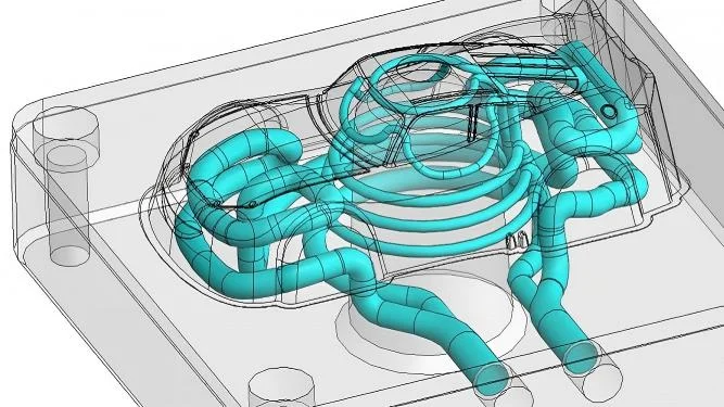
Conformal Cooling Channels
In injection molding, drilled cooling channels are straight lines. With SLM, we can print cooling channels that curve and twist inside the mold, following the exact contour of the part. This results in faster cycle times and better quality molded parts.
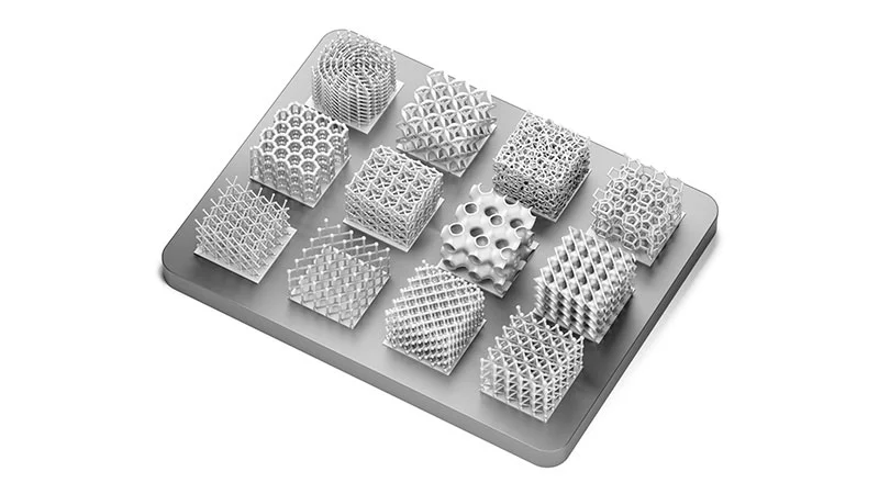
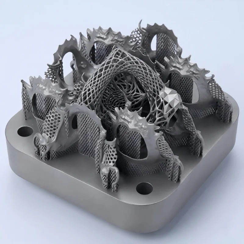
Lattice Structures
SLM can generate internal honeycombs or lattice micro-structures. This creates parts that are incredibly light yet stiff, or capable of specific energy-absorption properties (like crash structures), which is impossible to machine solid blocks.
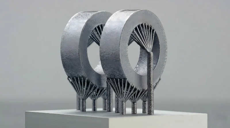
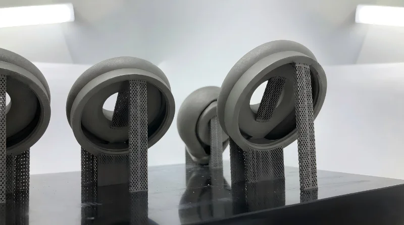
Thermal Dissipation (Heat Anchoring)
The laser generates immense heat. If a feature is built in isolation surrounded only by loose powder which is an insulator, it will overheat and warp. Supports act as a conduit to transfer heat away from the melt pool and into the build plate.
Preventing Deformation (Stress Relieving)
As metal cools, it contracts. Residual stresses try to curl the edges of the part up (telescoping). Strong supports anchor the part to the plate to maintain geometric accuracy.
Supporting Overhangs
Any surface angle below 45 degrees usually requires support to prevent the melt pool from sinking into the loose powder below. Using the "45-degree rule" in design can help minimize the need for supports, saving material and billing costs.

Aerospace & Aviation
Fuel nozzles, turbine blades, lightweight mounting brackets.
Consolidation of assemblies (printing 20 parts as 1 unit) reduces assembly time and failure points.

Medical & Dental
3D printed titanium medical implants (acetabular cups, spinal cages) and customized dental crowns.
SLM allows for porous lattice structures on the surface of implants, promoting osseointegration (bone growth into the implant).

Automotive
Heat exchangers, pistons with internal cooling galleries for Formula 1 and high-performance vehicles.
Rapid iteration of designs to improve thermal efficiency.

Tooling & Molding
Conformal cooling inserts.
Reducing cycle times by up to 30% through optimized cooling paths.
What Is Mold Inspection and How Can You Get It Right?
Key Takeaways Mold inspection is a systematic process of examining injection molds for dimensional accuracy, surface quality, and functional performance before and during production. Regular tooling inspections can reduce scrap

Metal Insert Injection Molding: Design & Defect Prevention
Key Takeaways Metal insert injection molding integrates metal components directly into plastic parts during molding for superior mechanical bond strength. Insert design—knurling, undercuts, wall thickness—is the primary driver of pull-out

Top 5 Injection Molding Companies in Pakistan
Key Takeaways Pakistan has an active plastics manufacturing sector centered around Karachi and Lahore, primarily serving domestic consumer goods, packaging, and automotive aftermarket markets. Precision injection molding capability for export-grade

