 Skip to content

Runners and gates are the circulatory system of any injection molding1 tool. They decide whether molten plastic reaches every cavity at the right temperature, pressure, and speed — or whether you end up with short shots, sink marks, and weld lines that scrap your parts. Every mold we build at ZetarMold goes through a runner and gate review before steel is cut, because getting these channels wrong is one of the fastest ways to burn through tooling budget and production time. In this guide, we break down the types of runners and gates, the design rules that matter most, and the most common mistakes we have seen across thousands of mold projects worldwide.
Whether you are specifying a brand new tool or troubleshooting an existing one, the practical principles here will help you make better design decisions and avoid the most common pitfalls that catch even experienced engineers off guard.
- Runners channel molten plastic from the machine nozzle to each cavity; gates control the final entry point.
- Hot runner systems eliminate waste but cost more; cold runners are simpler but leave scrap.
- Gate type, size, and location directly affect part quality, weld lines, and cosmetic appearance.
- Balanced runner layouts ensure uniform fill across multi-cavity molds.
- Early DFM review of the runner and gate system prevents costly mold rework.
What Are Runners and Gates in Injection Molding?
Runners and gates are two distinct but tightly connected features inside an injection mold2. The runner is the channel network that carries molten plastic from the machine nozzle or sprue to the vicinity of each cavity. The gate is the narrow opening at the very end of that channel where the melt enters the cavity itself.
For a broader view, our injection molding complete guide covers process fundamentals, material behavior, and production decisions.
Think of it this way: the runner is the highway, and the gate is the off-ramp. The highway needs to be wide enough to keep traffic flowing without excessive pressure drop, and the off-ramp needs to be sized so that material enters the cavity smoothly and freezes off at the right moment. Get either one wrong, and you are looking at defects, long cycle times, or wasted resin.
In practice, runners and gates are machined directly into the mold plates or into hot-runner manifolds. Their geometry is locked in at the tooling stage, which means mistakes are expensive to fix. A runner that is too long wastes material and increases cycle time. A gate that is too small creates excessive shear, burning the material or causing short shots. A gate placed in the wrong spot leaves a visible mark on a cosmetic surface or creates a weld line in a high-stress area.
The interaction between runner and gate also affects pack and hold pressure. If the gate freezes too early, the cavity cannot be adequately packed, leading to shrinkage and dimensional variation. If it stays open too long, the cycle drags on and you may see overpacking near the gate. This is why runner and gate design is one of the first things an experienced mold engineer evaluates during DFM review.
At ZetarMold, we review runner and gate layouts for every new mold before steel is cut. Our 8 senior engineers collectively have decades of experience across thousands of tooling projects, and they can spot potential fill issues in a runner layout that looks fine on paper but will cause problems in production.
How Do Different Runner Types Affect Part Quality?
The runner type you choose has a direct and measurable impact on material waste, cycle time, pressure consistency, and part-to-part variation. In our experience, the choice between cold runners and hot runners is the single biggest runner-related decision in any mold build.
Cold runners are machined into the mold plates themselves. The molten plastic flows through these channels and solidifies along with the part. After ejection, the runner is separated from the part and either reground and reused or scrapped. Cold runners are the default choice for low-to-medium volume production and for materials that are not sensitive to regrind. They are simpler to build and maintain, and the mold cost is lower.
The downside is material waste and cycle time. A large cold runner adds to the shot weight, which means more material to melt, inject, and cool every cycle. For a high-volume part running millions of cycles, that waste adds up fast. Cold runners also create more pressure drop than hot runners, which can be a problem for thin-walled parts or high-viscosity materials.

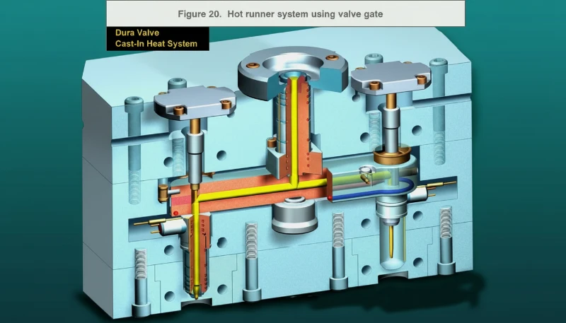
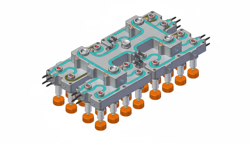
Hot runners use heated manifolds and nozzles to keep the plastic molten inside the runner channel at all times. There is no solidified runner to eject or scrap. The material savings alone can justify the higher mold cost for high-volume production. Hot runners also reduce cycle time because you are not waiting for a thick runner to cool, and they provide more consistent pressure at the gate.
However, hot runner systems are more complex. They add cost to the mold, they require temperature controllers, and they can be sensitive to material changes or color changes. Some materials — notably heat-sensitive resins like PVC or certain polyesters — are not ideal candidates for hot runners because the extended residence time in the manifold can cause degradation.
Within cold runners, the cross-sectional shape matters more than most people realize. A full-round runner has the best surface-area-to-volume ratio, meaning the least heat loss and pressure drop. A trapezoidal runner is easier to machine but has more surface area relative to volume, so the melt cools faster. A half-round runner is the worst of both worlds — we almost never recommend it. The runner diameter should be graduated, getting smaller as you move from the sprue toward the gate, to maintain flow front velocity and avoid dead spots.
What Are the Main Types of Gates in Injection Molding?
There are roughly a dozen gate types used in production molds, but six of them cover the vast majority of applications. Each has specific strengths and tradeoffs that make it suited for certain part geometries, materials, and production volumes.
The edge gate (also called a side gate or rectangular gate) is the workhorse of injection molding. It sits on the parting line at the edge of the cavity. The gate thickness is typically 30 to 50 percent of the nominal wall thickness, and the width is two to three times the thickness. Edge gates are easy to machine, easy to modify during sampling, and they work with virtually every thermoplastic. The downside is that they leave a visible gate vestige on the part edge, and they require a secondary trimming operation unless an automatic degating mechanism is built into the mold.
Pin gates are small-diameter gates, typically 0.8 to 1.5 mm, often used in three-plate molds. Because of their small size, they leave a minimal vestige and can be automatically separated from the runner during mold opening. Pin gates work well for small to medium parts, especially when you need multiple gates to fill a large or complex geometry. Their high shear rate makes them unsuitable for shear-sensitive materials like some glass-filled nylons.
Submarine gates (also called tunnel gates) route the gate through the mold steel below the parting line. When the mold opens and the part ejects, the gate shears off cleanly. This allows automatic degating on a two-plate mold, which is a significant advantage for high-volume production. The gate can enter the cavity from the side or from below, giving the designer flexibility in gate placement. The tradeoff is that the tunnel angle and geometry must be precisely machined, and the gate steel wears faster because the material is being forced through a sharp turn.
“Gate freeze time must be shorter than the overall cooling time to prevent backflow of molten material from the cavity.”True
If the gate does not freeze off before packing pressure is released, material can flow back out of the cavity, causing sink marks and dimensional variation.
“A larger gate always produces a higher-quality part.”False
An oversized gate extends cycle time because it takes longer to freeze, increases gate vestige size, and can cause overpacking near the gate. Gate sizing is a balance between fill speed, packing, and cycle efficiency.
Fan gates are used for flat, thin-walled parts where you need to distribute the flow across a wide front to avoid flow marks and jetting. The gate starts narrow at the runner and fans out to match the part width. Film gates are similar but extend across the full width of the part. Both types are excellent for optical parts and flat panels where cosmetic quality on the gate side matters. The disadvantage is that both leave a wide gate vestige that requires trimming, and they add to the runner volume.
Direct gates (also called sprue gates) feed straight from the machine nozzle into the cavity with no runner at all. They provide the lowest pressure drop and are used for single-cavity molds making large parts like appliance housings or automotive panels. The gate vestige is large and usually needs to be machined off. Direct gates also tend to cause high residual stress near the gate area because the packing pressure is concentrated there.
How Do You Design Runners and Gates for Multi-Cavity Molds?
The key to multi-cavity mold design is balancing flow so every cavity fills at the same time. Multi-cavity molds present a unique challenge: every cavity must fill at the same time, with the same pressure, and produce the same part. If one cavity fills first, it gets overpacked while the others are still filling. If one cavity is last, it may short. This is called fill imbalance, and it is the number one quality issue in multi-cavity production.
The solution is a balanced runner layout. In a naturally balanced layout, every cavity is equidistant from the sprue. The path length, runner diameter, and number of bends are identical for each cavity. This is the ideal, but it is not always possible — especially when cavities are different sizes or when the mold layout is constrained by the machine tie-bar spacing.
When a naturally balanced layout is not feasible, you use an artificially balanced layout. This means adjusting the runner diameters and gate sizes cavity by cavity so that the flow resistance is equal for every path. This requires mold flow simulation — we use Moldflow3 analysis at ZetarMold to predict fill patterns and optimize runner dimensions before cutting steel. Running simulation upfront is far cheaper than re-cutting runner channels after T1 sampling.
Runner layout also affects the mold size and the shot weight. A compact H-pattern runner for an 8-cavity mold is more efficient than a straight-line layout, but it requires more complex machining. A radial layout works well for round parts but can waste space for rectangular ones. The layout decision should be made early in the mold design process because it affects every downstream decision: cooling channel placement, ejection system design, and mold base size.
Gate sizing in multi-cavity molds must also account for cavity position. In a naturally balanced layout, all gates are the same size. In an artificially balanced layout, the gates closer to the sprue are smaller to increase flow resistance and equalize fill time. This is one reason why the initial mold sampling process is critical — you need to verify the actual fill balance and adjust gate sizes if necessary. At our Shanghai factory, we routinely run mold flow simulations on multi-cavity tools and validate the results during first article sampling on our 47 injection molding machines.
At our Shanghai facility, ZetarMold runs 47 injection molding machines ranging from 90T to 1850T, with an in-house tooling shop that designs and validates runner systems using UG, SOLIDWORKS, and MOLDFLOW before steel is cut.
Why Does Gate Location Matter for Part Quality?
Gate location is the most important decision in mold design because it determines the flow path, weld lines, and warpage direction. The flow path controls where weld lines form, how the part packs, where sink marks appear, and whether the cosmetic surface is acceptable. Get the gate location wrong, and even an otherwise well-designed mold will produce defective parts.

The first rule of gate location is to place the gate where it will not be visible on the primary cosmetic surface. For consumer products, the gate vestige is usually hidden on the back or inside a snap-fit feature. For automotive parts, it may be concealed under a trim panel. If the gate must be on a visible surface, consider a valve gate or a submarine gate to minimize the vestige.
The second rule is to gate into the thickest section of the part and let the flow move toward the thinner sections. This ensures that the thick sections are packed before the thin sections freeze off, preventing sink marks and voids. Gating into a thin section and trying to pack a thick section through it is a recipe for sink and short shots.
The third rule is to position the gate so that weld lines end up in non-critical areas. A weld line forms wherever two flow fronts meet. If you have a single gate, there is no weld line from the gate itself, but there may be weld lines around holes or inserts. With multiple gates, the weld line forms between the gates. Using mold flow simulation to predict weld line location is standard practice — and it should be.
In our experience, one of the most common mistakes we see from less experienced mold makers is gating on a cosmetic surface to save tooling cost, then spending far more money on secondary finishing to remove the gate mark. The right approach is to design the gate location into the part from the beginning, during DFM, so that both the part designer and the mold maker agree on where the vestige will be and whether it is acceptable.
What Are the Key Design Checks for Runners and Gates?
The most effective approach is a standardized design checklist that every runner and gate system must pass before production. At ZetarMold, we use a 25-point check that covers everything from runner balance to gate steel hardness. Here are the most critical checks that catch the most problems.
First, verify runner balance. Run a mold flow simulation and check that all cavities fill within 5 percent of each other in both fill time and pressure. If the imbalance is larger, adjust runner diameters or gate sizes before cutting steel. Second, check the gate-to-wall-thickness ratio. For edge gates, the gate thickness should be 30 to 50 percent of the nominal wall. For pin gates, the diameter should be 0.8 to 1.5 mm depending on material viscosity and part size. Third, verify that the gate freeze time is shorter than the packing time but long enough to allow adequate cavity packing. This is a simulation output that must be checked.
Fourth, confirm that the runner can be ejected cleanly. The runner must have adequate draft, and the ejector pins must engage the runner at the right locations. A runner that hangs in the mold after opening will cause downtime and potential mold damage. Fifth, check the gate vestige height against the part specification. Some parts, especially those that mate with other components, have strict requirements on gate vestige height. If the vestige is too tall, it will interfere with assembly.
Sixth, review the gate steel selection and hardness. Gates experience high wear, especially with glass-filled materials. The gate insert should be made from hardened steel — we typically use H13 or S136 at 48-52 HRC for production molds. Seventh, verify that the air in the cavity can escape ahead of the melt front. The gate location determines the flow direction, which determines where the air is pushed. If air is trapped in a dead-end area with no vent, you will get burns and short shots.
Finally, check the runner weight against the part weight. In a well-designed cold runner mold, the runner weight should be no more than 30 to 50 percent of the total shot weight. If the runner is heavier than the part, you are wasting material and cycle time, and you should consider a hot runner or a layout redesign. These checks are standard in our tooling process — our in-house mold manufacturing facility supports over 100 mold sets per month, and every one goes through this review.
“Mold flow simulation can predict weld line locations before the mold is built.”True
Simulation tools like MOLDFLOW model the flow front advancement and show exactly where flow fronts converge, allowing designers to relocate gates or add flow leaders to move weld lines to non-critical areas.
“Runner diameter does not need to change along the flow path.”False
Runner channels should be graduated — wider near the sprue and narrower toward the gates — to maintain flow velocity and avoid dead spots where cold material accumulates.
How Can Factory Expertise Prevent Runner and Gate Defects?
Factory expertise is what separates a well-designed mold from consistent, defect-free production. Even a perfectly designed runner and gate system can produce defective parts if the factory lacks the expertise to maintain the process correctly. The quality of the equipment and the rigor of the production control system make the difference.
Process setup is where most runner-and-gate problems actually manifest. A technician who does not understand how gate freeze time interacts with pack pressure will set the wrong holding time, leading to either sink marks or flash. A technician who does not know that a submarine gate requires a specific ejection speed may set the press too slow, causing the gate to stretch rather than shear cleanly. These are not theoretical problems — we have fixed molds from other suppliers where the runner was fine but the process window was never established correctly.
Material handling is another factor that is often overlooked. Moisture in hygroscopic materials like nylon or polycarbonate causes splay and weak weld lines at the gate. If the dryer is not maintained at the right temperature and dew point, the gate area — where the melt is moving fastest and shear is highest — will show the defect first. In our factory, every press is connected to a hopper dryer, and we verify material moisture content before every production run with 400+ plastic materials in our experience database.
Tooling maintenance matters just as much. Gates wear down over time, especially with abrasive materials. A pin gate that starts at 1.0 mm may open up to 1.3 mm after 100,000 cycles with glass-filled nylon, changing the fill pattern and causing flash or dimensional drift. Regular mold maintenance — measuring gate dimensions, polishing runner channels, checking ejector pin alignment — is essential for consistent quality. This is one reason why we maintain an in-house mold manufacturing facility: we can service and rebuild molds quickly without waiting for an outside vendor.
With 20+ years of injection molding and tooling experience, ZetarMold has built production control systems that catch these issues before they reach the customer. Our engineering team reviews every mold design, runs mold flow analysis on complex tools, and establishes documented process parameters that are locked before production starts. If you are evaluating injection molding partners, the key question to ask is whether the factory can explain their runner and gate design rationale — not just show you a mold drawing, but explain why each decision was made and how they verify it during sampling.
Get Expert Runner and Gate Design for Your Next Mold
Runners and gates are too important to leave to chance. A poorly designed gate can turn a good part design into a production nightmare — visible defects, dimensional instability, high scrap rates, and slow cycles. At ZetarMold, our 8 senior engineers review every mold design with full MOLDFLOW simulation on our 47 presses from 90T to 1850T in our Shanghai factory. Whether you need a single-cavity prototype mold or a 32-cavity production tool, we deliver optimized runner and gate systems that work from shot one.
Ready to start? Send us your 3D model and get a free DFM review with runner and gate recommendations within 48 hours. Get a Free Quote and see why companies trust ZetarMold for precision injection molding from China.
Frequently Asked Questions
What is the difference between a runner and a gate in injection molding?
A runner is the channel that carries molten plastic from the machine nozzle or sprue to the area near the cavity. A gate is the narrow opening at the end of the runner where the melt actually enters the cavity. Think of the runner as the highway and the gate as the exit ramp. The runner handles bulk material transport, while the gate controls flow rate, direction, and freeze-off timing. Both must be designed together as an integrated system because changing one directly affects the performance of the other in production.
What are the most common types of gates used in injection molding?
Runner balancing ensures all cavities fill simultaneously with equal pressure. In a naturally balanced layout, every cavity is the same distance from the sprue with identical runner geometry. When natural balance is not possible due to cavity layout constraints, artificial balancing adjusts runner diameters and gate sizes cavity by cavity to equalize flow resistance. Mold flow simulation software like MOLDFLOW is essential for predicting fill patterns and optimizing dimensions before the mold is built, saving significant rework costs during sampling.
How do you balance runners in a multi-cavity mold?
Gate location determines the direction of melt flow inside the cavity, which directly controls where flow fronts meet and form weld lines. When multiple gates are used, weld lines form between the flow fronts from adjacent gates. A weld line is inherently weaker than the surrounding material because the two flow fronts may not bond completely. By using mold flow simulation to predict weld line positions and strategically placing gates during DFM review, designers can move weld lines to non-critical areas where structural strength is less important.
Why does gate location affect weld lines in injection molding?
Gate location determines the direction of melt flow inside the cavity, which directly controls where flow fronts meet and form weld lines. When multiple gates are used, weld lines form between the flow fronts from adjacent gates. A weld line is inherently weaker than the surrounding material because the two flow fronts may not bond completely during cooling. By using mold flow simulation to predict weld line positions and strategically placing gates during DFM review, designers can move weld lines to non-critical areas where structural strength is less important.
What happens if a gate is too small in injection molding?
A gate that is too small creates excessive shear stress as the melt is forced through the narrow opening. This can cause material degradation, especially with shear-sensitive resins. The high pressure drop also increases the risk of short shots where the cavity does not fill completely. Additionally, an undersized gate may freeze off before packing is complete, leading to sink marks, voids, and dimensional variation. Gate sizing must balance fill speed, packing time, and shear limits for the specific material being used.
How does a hot runner system differ from a cold runner system?
A hot runner system uses heated manifolds and nozzles to keep plastic molten inside the runner channels, so there is no solidified runner waste to eject or scrap. A cold runner system relies on unheated channels in the mold plates where the runner solidifies with the part and must be separated after ejection. Hot runners save material and reduce cycle time but increase mold cost and complexity. Cold runners are simpler and cheaper to build but generate scrap. The choice depends on production volume and part economics.
What is gate freeze time and why does it matter?
Gate freeze time is the time it takes for the material at the gate to solidify enough to seal off the cavity from the runner. This is critical because it determines when packing pressure can be released without material flowing back out. If the gate freezes too early, the cavity is underpacked, causing sink marks and dimensional variation. If it freezes too late, cycle time increases and overpacking near the gate can cause flash or distortion. Proper gate sizing controls freeze time effectively.
How do you prevent gate vestige from affecting part appearance?
Gate vestige can be minimized through several strategies: use submarine or pin gates for small clean break points; place gates on non-cosmetic surfaces or inside features where the vestige is hidden; use valve gates for a flush finish on visible surfaces; specify gate vestige height requirements on the part drawing; and optimize gate geometry and processing conditions to reduce the vestige size. Discuss gate location and vestige requirements with your mold maker during the DFM phase to avoid expensive post-molding finishing operations.
-
injection molding: Injection molding is a manufacturing process that produces parts by injecting molten material into a mold, widely used for mass-producing plastic components with high precision. ↩
-
injection mold: An injection mold is a precision tool defining cavity geometry, cooling layout, ejection system, and gate configuration for producing molded parts. ↩
-
Moldflow: Moldflow is a plastics injection molding simulation software that predicts fill patterns, weld lines, sink marks, and warpage before tooling is built. ↩


