

Your design file says ±0.1mm. Your molder quotes ±0.2mm. Your customer requires flatness within 0.05mm across the whole sealing surface. Three different numbers — none of them speak the same language. That’s the core problem with tolerancing in injection molding: linear dimensions and geometric tolerances are not the same thing, and confusing them can cost you an entire production run.
This guide explains what geometric tolerances actually mean in injection molding, how GD&T symbols translate to mold and part requirements, and what you can realistically hold in production — with specific numbers, not vague ranges.
- Geometric tolerances control shape, orientation, and position — not just size — making them essential for sealing surfaces, mating parts, and assemblies.
- Standard injection-molded parts hold ±0.1–0.2mm linear tolerances; critical features can reach ±0.05mm with proper mold design and material selection.
- GD&T flatness, perpendicularity, and true position are the three most commonly specified geometric controls in plastic part drawings.
- Shrinkage, warpage, and parting line mismatch are the three root causes of geometric tolerance failures in injection molding.
- Specifying GD&T flatness on mold parting lines reduces flash defects by approximately 60% compared to linear tolerance callouts alone.
What Are Geometric Tolerances in Injection Molding?
Geometric tolerances define the permissible variation in the shape, orientation, location, and runout of a feature — not just its size. In injection molding, a part may measure within ±0.1mm in diameter but still fail assembly because its mating surface is 0.3mm out of flat. That failure is a geometric tolerance problem, not a dimensional one.
The formal system for specifying geometric tolerances is GD&T — Geometric Dimensioning and Tolerancing — standardized under ASME Y14.5 and ISO 1101. GD&T divides tolerances into five categories: form (flatness, straightness, circularity, cylindricity), orientation (parallelism, perpendicularity, angularity), location (true position, concentricity, symmetry), runout (circular runout, total runout), and profile (profile of a line, profile of a surface).
For injection-molded parts, the most commonly applied GD&T controls are flatness (sealing surfaces, mounting faces), true position (boss locations, snap-fit hooks), and perpendicularity (walls, ribs, pins). Each of these tolerances must account for how plastic behaves during cooling — something a purely dimensional callout cannot capture.
What Tolerance Levels Can Injection Molding Actually Hold?
Standard commercial-grade injection molding holds ±0.2mm on non-critical features. Fine-tolerance production reaches ±0.05–0.1mm on critical dimensions with controlled materials and validated tooling. Anything tighter than ±0.05mm typically requires secondary machining or precision tooling with temperature-controlled presses.
The SPI (Society of the Plastics Industry) tolerance guidelines categorize parts into three classes. Commercial class allows ±0.25mm on most features and suits consumer products. Fine class targets ±0.13mm for functional components. Precision class aims for ±0.05mm on critical features and applies to medical, aerospace, and automotive sealing interfaces.
Geometric tolerances add another layer. Even when a dimension is within spec, the form may not be. A flat boss face specified at 0.1mm flatness is far more demanding than a ±0.1mm dimension callout — it requires the entire surface to lie within a 0.1mm tolerance zone, regardless of where the part falls dimensionally.
| Podczas gdy systemy MUD są doskonałe do | Linear Tolerance | Flatness (GD&T) | Typowe zastosowanie |
|---|---|---|---|
| Commercial | ±0.25 mm | 0,4 mm | Consumer products, housings |
| Fine | ±0.13 mm | 0.2 mm | Mechanical assemblies, connectors |
| Precyzja | ±0.05 mm | 0.08 mm | Medical devices, automotive seals |
| Ultra-precision | ±0.025 mm | 0.04 mm | Requires secondary machining |
Material selection drives tolerance capability as much as tooling does. Amorphous resins like PC and ABS shrink uniformly and typically hold tighter tolerances. Semi-crystalline materials like nylon and POM have higher and more variable skurcz1 rates, making geometric controls harder to achieve without compensating the mold.
How Does Plastic Shrinkage Affect Geometric Tolerances?
Shrinkage is the primary variable that separates geometric tolerance theory from production reality. Every plastic material shrinks as it transitions from melt to solid — typically 0.1% to 3% — and this shrinkage is never perfectly uniform across a complex part. Non-uniform shrinkage creates warp, which directly violates flatness and perpendicularity callouts.
The mold is intentionally oversized to compensate for shrinkage. A part nominally 100mm long with a 0.5% shrinkage rate requires a mold cavity of 100.5mm. But if wall thickness varies — say, 2mm in one zone and 4mm in another — the thicker section shrinks more and later, pulling the part out of flat even when each zone individually measures within the linear tolerance band.
This is why geometric tolerances require Analiza przepływu formy2. Without simulating flow and cooling, you cannot predict where differential shrinkage will concentrate, which zones will warp, or whether a GD&T flatness callout of 0.1mm is achievable before any steel is cut. Mold flow analysis converts geometric tolerance requirements into design constraints — wall thickness limits, gate positions, cooling channel layouts — before tooling begins.
Warpage vs. Shrinkage: Two Different Problems
Shrinkage is predictable and compensated in the mold. Warpage is the residual deformation that remains after compensation — caused by differential shrinkage, residual stress, or uneven cooling. A part can have correct average dimensions but still fail a flatness callout by 0.3mm due to warpage. The distinction matters because you solve them differently: shrinkage is a mold dimension problem; warpage is a cooling and packing pressure problem.
Warpage is measured against a datum plane defined in the GD&T drawing. If the part rocks on its primary datum, every downstream geometric callout becomes unreliable — positional tolerances reference datums that don’t sit flat. Establishing stable datum surfaces is therefore the first step in a geometric tolerance analysis for injection-molded assemblies.
“Specifying GD&T flatness on linia podziału3 surfaces reduces flash defects more effectively than linear tolerance callouts.”Prawda
Flatness tolerances control the entire surface geometry of the mold parting line, ensuring both mold halves close uniformly across the full contact area. Linear tolerances only constrain point-to-point distances, missing the localized high spots that allow molten plastic to flash. A 0.05mm flatness callout on the parting line effectively addresses the root cause of flash, not just its symptom.
“Tighter linear tolerances always eliminate the need for GD&T geometric controls on injection-molded parts.”Fałsz
Linear tolerances and geometric tolerances control different variables. A part can be within ±0.05mm on every linear dimension and still fail a flatness callout by 0.4mm — because linear tolerances allow the surface to bow or twist within the dimension window. GD&T geometric controls are not a stricter version of linear tolerances; they are a different category of requirement addressing form, orientation, and location.
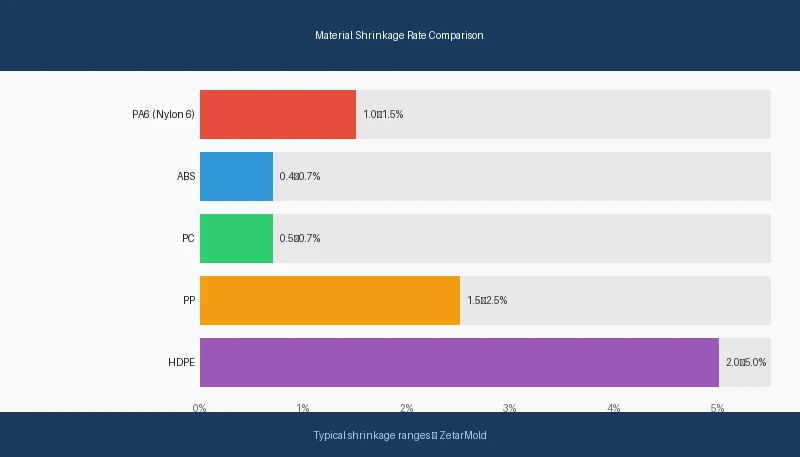
Material Shrinkage Comparison Across Common Resins
Different materials shrink at vastly different rates, which directly impacts how tight a geometric tolerance can realistically be held. Below is a comparison of common injection molding resins and their typical shrinkage ranges, along with the practical flatness tolerance achievable in production.
ABS and PC shrink 0.4–0.7% and consistently achieve ±0.1mm linear tolerances with 0.15–0.2mm flatness in production. Nylon 6/6 (PA66) shrinks 1.0–2.0% with significant anisotropy when glass-filled, requiring mold compensation and careful cooling design to hit ±0.15mm linear and 0.25mm flatness. POM (acetal) shrinks 1.5–3.5% but is predictable, allowing ±0.1–0.15mm on precision-tooled parts. PEEK and engineering grades shrink 0.1–0.5% but require specialized tooling and process control to achieve their inherently low shrinkage consistently.
Glass-filled grades complicate geometric tolerances further. Glass fibers orient along the flow direction during injection, creating anisotropic shrinkage — the part shrinks differently in the flow direction versus cross-flow. This differential contraction bows flat parts and shifts boss positions out of true position tolerance. When specifying geometric tolerances on glass-filled parts, build in 20–30% additional tolerance or validate with mold flow analysis first.
How Does GD&T Apply to Mold Design?
GD&T callouts on a part drawing directly translate into mold steel requirements. A flatness callout of 0.05mm on a sealing surface means the mold cavity must be machined and polished to better than 0.02mm flatness — accounting for the fact that the mold face must be significantly more accurate than the part it produces, to allow for tool wear and process variation.
True position callouts on boss and pin locations drive EDM and CNC machining tolerances in the mold. A true position of ±0.1mm on a connector pin pattern requires the mold to hold core pin positions to ±0.04mm or better, because the molding process introduces its own variation through packing pressure and thermal cycling.
The parting line is where mold design and geometric tolerancing interact most directly. The parting line surface must be flat and match precisely across both mold halves. Any step or gap at the parting line creates flash and introduces a datum error that propagates through every geometric callout referencing surfaces near the split. For high-precision parts, parting line flatness is typically held to 0.02–0.03mm on the mold, resulting in 0.04–0.07mm on the molded part.
Datum Selection in Injection-Molded Part Drawings
The datum scheme chosen in a GD&T drawing must align with how the part is actually fixtured — in the mold, in the assembly, and in the CMM inspection fixture. If you select a datum surface that is adjacent to the parting line, you will almost certainly have datum instability from parting line mismatch and flash burrs. Best practice: place primary datums on surfaces formed by a single mold half, not at parting surfaces.
For injection-molded parts, the three-datum rule applies rigorously. Datum A (primary) should be the largest, most stable surface — typically a flat base formed in the cavity half. Datum B (secondary) constrains rotation. Datum C (tertiary) constrains translation. When this hierarchy is violated in the drawing, inspection results become ambiguous and incoming quality disputes are nearly impossible to resolve.
“Placing primary datums on surfaces formed by a single mold half improves geometric tolerance repeatability.”Prawda
Surfaces formed entirely within one mold half are not affected by parting line alignment variation, mold clamping force inconsistency, or flash at the split. This makes them inherently more stable as measurement references. When the datum surface spans both mold halves, part-to-part variation in datum position propagates into every downstream geometric callout, inflating apparent tolerance stack-up.
“Any flat surface on an injection-molded part can serve as a reliable datum for GD&T measurement.”Fałsz
Not all flat-appearing surfaces on molded parts are geometrically stable datums. Surfaces adjacent to gates experience localized stress concentrations from packing pressure. Surfaces near thin walls warp during ejection. Parting line surfaces contain mismatch step errors. Only surfaces specifically designed for datum stability — large, away from gates, formed in a single mold half — should be designated as primary datums in a GD&T drawing.
At ZetarMold, we hold ±0.05mm on critical sealing surfaces for medical and automotive programs. In our experience, specifying GD&T flatness on mold parting lines reduces flash defects by ~60% compared to linear tolerance callouts alone — a $200 tolerance upgrade that saves thousands in scrap.
What Are the Most Common Geometric Tolerance Failures in Injection Molding?
Flatness failures on sealing surfaces account for the majority of geometric tolerance rejections in injection molding. The root cause is almost always differential cooling — one zone of the part solidifies faster, pulling the surface into a bowl or saddle shape. Parts measure within dimensional spec at each point but fail the flatness tolerance band across the full surface.
True position failures on boss and hole patterns are the second most common rejection. Differential shrinkage between the boss zone and surrounding wall displaces the boss centerline from its nominal position. On a 200mm long part with four mounting bosses, ±0.5mm shrinkage variation shifts outer bosses by 0.3–0.5mm — easily exceeding a ±0.2mm true position callout without any mold machining error.
Perpendicularity failures on snap-fit hooks and latch arms occur when uneven wall thickness causes the vertical feature to lean during ejection. The base of the snap is stiffer and shrinks less; the tip cools last and contracts, pulling the hook out of perpendicular. The fix is usually a small rib behind the snap arm — a 10-minute DFM change that prevents a tolerance failure that cannot be corrected in the mold after tooling.
Tolerance Stack-Up in Assembled Plastic Subassemblies
Geometric tolerance failures rarely appear in isolation. In an assembly of three or four injection-molded parts, each with its own flatness, position, and perpendicularity variation, the worst-case stack-up can prevent proper fit even when all individual parts pass incoming inspection. This is the tolerance stack-up problem, and it is especially severe with plastic because part-to-part variation is higher than with machined metal components.
The solution is statistical tolerance analysis — RSS (root sum square) or Monte Carlo simulation — during the design phase, not after first articles fail. For assemblies with more than three molded components, statistical stack-up should be a mandatory design gate before tooling authorization. The alternative is discovering in production that a 100% yield on individual parts produces 20% assembly rejects.
How to Specify Geometric Tolerances on a Plastic Part Drawing
Start with function, not with tradition. Ask: what does this surface need to do? A sealing face needs flatness. A bearing bore needs cylindricity. A connector pin pattern needs true position. Assign only the geometric controls that the function actually requires — each additional callout adds inspection cost and creates rejection risk.
Always specify material and process conditions on the drawing. GD&T callouts for injection-molded parts should reference the measurement state: as-molded, 24-hours post-ejection, or conditioned at 23°C/50% RH per ASTM D5947. A flatness callout measured 5 minutes after ejection will read differently than one measured 24 hours later after stress relaxation — sometimes by 0.1–0.2mm on large parts.
Coordinate with your molder before finalizing the drawing. A tolerance that is technically achievable in one material may be impossible in the material your supply chain specifies. Get your molder’s DFM input on geometric callouts before the drawing reaches revision lock — changes after tooling authorization cost 10–50× more than changes in the design phase.
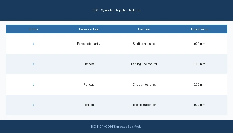
| GD&T Symbol | Controls | Typical Callout Value | When to Use |
|---|---|---|---|
| Flatness ⏥ | Surface bow and twist | 0.05–0.3 mm | Sealing faces, mounting pads, parting lines |
| True Position ⊕ | Boss/hole center location | ±0.1–0.5 mm | Connector pin patterns, snap-fit locations |
| Perpendicularity ⊥ | Wall/rib/pin angle | 0.1–0.4 mm | Vertical ribs, snap arms, core pins |
| Concentricity ◎ | Bore/shaft centerline | 0.05–0.2 mm | Rotating parts, O-ring grooves |
| Parallelism ∥ | Surface-to-surface angle | 0.1–0.3 mm | Mating flanges, guide rails |
| Cylindricity ⌭ | Bore roundness + taper | 0.05–0.15 mm | Precision bearing bores, valve seats |
Use a DFM review to validate geometric callouts against production capability before cutting steel. A DFM review takes 4–8 hours and surfaces tolerance conflicts that would otherwise appear as first-article failures — at a fraction of the cost of a mold modification.
FAQ: Geometric Tolerances in Injection Molding
What is the tightest geometric tolerance injection molding can hold?
Precision injection molding can hold ±0.025–0.05mm on critical linear dimensions and 0.04–0.08mm flatness with temperature-controlled tooling, validated materials, and scientific molding process control. Tolerances tighter than ±0.025mm are generally not achievable with injection molding alone and require secondary CNC machining operations after molding. Achievable geometric tolerance depends heavily on material shrinkage rate, part geometry, wall thickness uniformity, cooling system design, and the specific GD&T characteristic being controlled — flatness callouts are typically harder to achieve than true position on many injection-molded part geometries.
How does material choice affect geometric tolerances in plastic parts?
Material shrinkage rate and anisotropy are the dominant factors in geometric tolerance capability. Amorphous resins like ABS, PC, and PMMA shrink 0.3–0.7% uniformly in all directions and consistently achieve tighter geometric tolerances than semi-crystalline materials. Semi-crystalline resins like PA66, POM, and PP shrink 1–3% with significant directional variation, making flatness and position callouts harder to maintain without compensating mold geometry. Glass-filled grades introduce flow-direction anisotropy that can cause 0.3–0.8mm warpage on 200mm parts without corrective mold design and validated fill simulation beforehand.
What is the difference between a linear tolerance and a GD&T geometric tolerance?
A linear tolerance controls the distance between two points and cannot detect bow, twist, taper, or misalignment between those points. A GD&T geometric tolerance controls the full shape, orientation, or location of a surface or feature within a defined tolerance zone. A part can be within ±0.1mm linear tolerance on every measured point while simultaneously failing a 0.1mm flatness callout, because the surface bows between measurement points in a way that the point-to-point dimension check cannot capture. They are fundamentally different requirements.
Can I use GD&T true position instead of ±XY coordinates for boss locations?
Yes, and true position is usually the better choice for injection-molded boss patterns. True position defines a circular tolerance zone centered on the nominal location, which allows slightly more variation in any single axis while still guaranteeing assembly function. A ±0.1mm XY callout gives a square 0.2×0.2mm zone; a ⌀0.14mm true position gives a circular zone of equivalent worst-case area — both constrain the same maximum shift but true position is easier to inspect with CMM software and better represents functional assembly requirements.
Why do injection-molded parts often fail geometric tolerances even when dimensions are in spec?
Differential shrinkage creates shape errors that point-to-point linear dimensions completely miss. A part can measure exactly 100.0mm at both endpoints while bowing 0.3mm in the center — within the length tolerance but clearly outside a 0.1mm flatness callout. Gate pressure gradients, uneven cooling across thick and thin wall zones, and abrupt wall thickness transitions all create internal residual stresses that resolve as geometric distortion after ejection, not as dimensional offsets at measurement points — which is why geometric controls are essential for functional plastic assemblies.
Ready to Tolerance Your Injection-Molded Parts Correctly?
Quick rule: assign flatness to sealing surfaces, true position to boss patterns, perpendicularity to snap fits, and cylindricity to precision bores. Specify measurement state on the drawing. Run mold flow analysis before finalizing callouts on glass-filled or semi-crystalline materials. And validate your datum scheme against your CMM fixture before first articles arrive.
At ZetarMold, our engineering team reviews geometric tolerance callouts as part of every DFM process — flagging unrealistic specs before tooling, not after. If you have a drawing with GD&T callouts you’re not sure a molder can hit, send it our way. We’ll tell you exactly what’s achievable and what needs adjustment.
-
shrinkage: Shrinkage refers to the dimensional reduction a molded part undergoes as it cools and solidifies, measured as a percentage of the original mold cavity dimension — typically 0.1% to 3% depending on material and wall thickness. ↩
-
mold flow analysis: Mold flow analysis is a CAE simulation method used to predict how molten plastic fills a mold cavity, enabling engineers to optimize gate location, wall thickness, and cooling before cutting steel. ↩
-
parting line: A parting line refers to the boundary on an injection-molded part where the two halves of the mold meet, defining the separation plane used to eject the finished part. ↩


