 Skip to content
Multi Jet Fusion (MJF) 3D Printing Services
Discover our professional Multi Jet Fusion (MJF) 3D printing services for strong, detailed parts with rapid lead times.

Resources for The Complete Guide to Multi Jet Fusion (MJF) 3D Printing
What Is Multi Jet Fusion (MJF) 3D Printing?
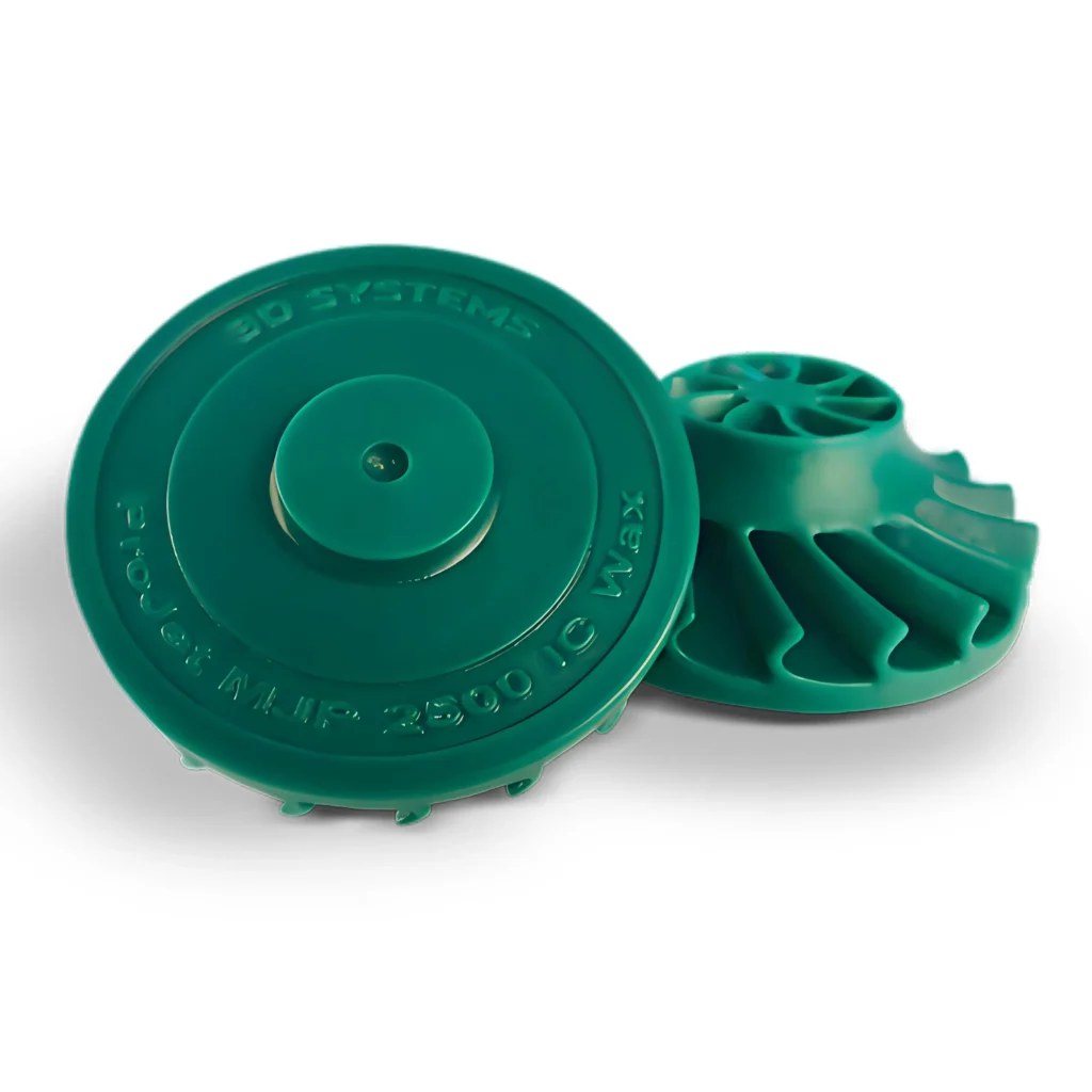
Multi Jet Fusion (MJF) is a high-speed, industrial-grade additive manufacturing technology developed and introduced by HP (Hewlett-Packard). It belongs to the powder bed fusion family of 3D printing processes. At its core, MJF builds functional prototypes and end-use production parts from a granular thermoplastic powder, layer by layer, with a level of speed, detail, and part quality that positions it as a leading technology for both rapid prototyping and serial production.
Unlike other powder bed fusion methods that use a single laser to trace and sinter a part’s geometry (like SLS), MJF employs a unique, area-wide process. It uses an inkjet array to selectively apply chemical agents across the entire surface of the powder bed in a single pass. This fundamental difference is the key to its exceptional speed and productivity, enabling the production of robust, high-quality parts at a lower cost per part compared to many alternatives.
1. The Core Principle: Powder Bed Fusion with a Detailing Agent:
The innovation of MJF lies in its use of two primary liquid agents: a Fusing Agent and a Detailing Agent.
- Fusing Agent: This is a black, thermally conductive ink. It is precisely jetted onto the areas of the powder bed that are intended to become the solid part. When infrared energy is applied, this agent absorbs the heat, causing the underlying powder particles to melt and fuse together.
- Detailing Agent: This agent is jetted around the outer contour of the part. Its primary function is to inhibit fusion. It acts as a thermal insulator, preventing the powder on the part’s boundary from melting. This creates a sharp thermal transition between the fused and unfused zones, resulting in crisp edges, fine feature definition, and a smoother surface finish than would otherwise be possible.
This dual-agent system gives MJF voxel-level control over the part’s properties, which is a cornerstone of the technology’s potential for future material and property developments.
2. How MJF Stands Apart in the Additive Manufacturing Landscape:
MJF is not merely an incremental improvement over existing technologies; it represents a paradigm shift in powder-based 3D printing. It bridges the gap between the design freedom of 3D printing and the manufacturing efficiency required for production.
- For Prototyping: It offers the ability to create highly functional, durable prototypes that closely mimic the mechanical properties of final injection-molded parts.
- For Production: Its speed, consistency, and cost-effectiveness make it a viable alternative to traditional manufacturing methods like injection molding for low-to-medium volume production runs, custom parts, and complex geometries that are impossible to mold.
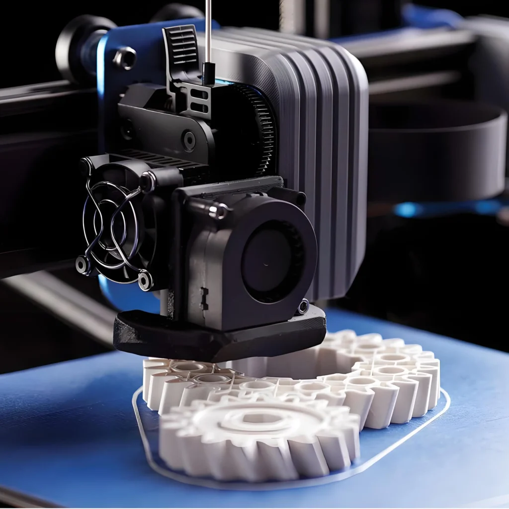
How Does Multi Jet Fusion Technology Work?
1. The Step-by-Step MJF Printing Process:
Step 1: Material Deposition
The process begins inside the build chamber. A re-coater mechanism sweeps a thin, precise layer of thermoplastic powder (e.g., PA 12) across the build platform, creating a fresh, uniform powder bed. The chamber is preheated to a temperature just below the material’s melting point, which minimizes the energy required for fusion and helps prevent warping.
Step 2: Agent Application
This is the defining step of the MJF process. An inkjet printhead, similar to those found in 2D paper printers but far more advanced, passes over the powder bed. This carriage contains thousands of nozzles that can jet tiny droplets (picoliters) of the chemical agents with extreme precision. As it moves, it performs two actions simultaneously:
- The Role of the Fusing Agent: The printhead selectively deposits the fusing agent onto the areas of the powder that correspond to the part’s cross-section for that specific layer. This agent is engineered to be a highly effective infrared radiation absorber. It essentially “paints” the slice of the 3D model onto the powder.
- The Role of the Detailing Agent: Simultaneously, the printhead applies the detailing agent around the perimeter of the part’s geometry. This agent has properties that inhibit fusion. It cools the boundary, preventing heat from spreading and partially melting the surrounding loose powder. This precise thermal control is what allows MJF to achieve sharp edges and fine details.
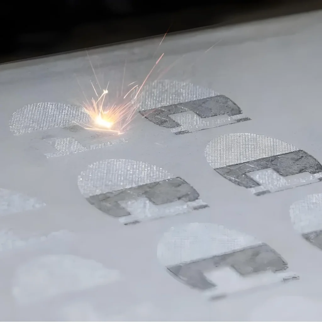
Step 3: Energy Application and Fusing
Immediately after the agents are applied, an infrared energy source (a set of high-powered lamps) passes over the entire powder bed. The areas treated with the black fusing agent absorb this energy rapidly, causing their temperature to rise above the material’s melting point. The powder in these areas melts and fuses together into a solid layer. The untreated powder and the areas treated with the detailing agent do not absorb as much energy and remain as loose powder.
Step 4: Layer Completion and Repetition
Once the layer is fused, the build platform lowers by the thickness of a single layer (typically around 80 microns). The re-coater then deposits a new layer of powder on top, and the entire cycle (Steps 1-4) repeats. This process continues layer by layer until the entire part or batch of parts is completed. Because the parts are supported by the surrounding unfused powder, no dedicated support structures are needed, allowing for complex geometries and the ability to nest multiple parts within the build volume to maximize efficiency.
2. Post-Printing: The Cooling and Unpacking Process:
Once the printing phase is complete, the entire build unit, containing the fused parts and the surrounding loose powder, is moved from the printer to a separate processing station.
- ① Controlled Cooling: The build unit must cool down slowly and under controlled conditions. This is a critical step to ensure part accuracy and optimal mechanical properties. Rushing the cooling process can lead to warping and internal stresses. This cooling period is a significant part of the overall MJF workflow and can take several hours.
- ② Part Extraction: After cooling, the build unit is unpacked. The block of fused parts and unfused powder is broken up. The large majority of the loose powder is removed and collected for recycling.
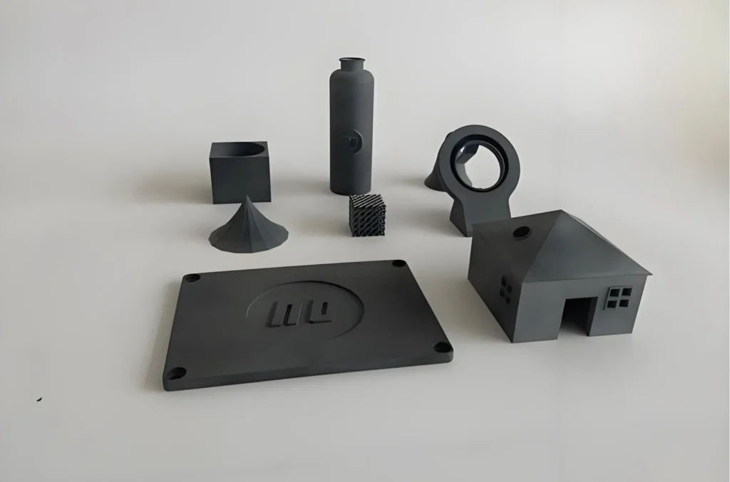
- ③ Powder Removal: The parts are then moved to a cleaning station where any remaining unfused powder is meticulously removed, typically using bead blasting or compressed air. This reveals the finished parts, which have a slightly rough, matte gray surface finish.

The reclaimed powder is mixed with a certain percentage of fresh powder (a process called “refreshing”) and can be used in subsequent builds. This high reusability rate (typically 80-90%) makes MJF a more sustainable and cost-effective process compared to other powder bed technologies that have lower refresh rates.
What Are the Typical Applications of MJF?
The unique combination of speed, cost-effectiveness, and robust material properties makes Multi Jet Fusion a highly versatile technology suitable for a vast range of applications, spanning the entire product lifecycle.
1. Functional Prototyping:
MJF excels at creating high-fidelity, functional prototypes that can withstand rigorous testing.
- Form, Fit, and Function Testing: Engineers can produce prototypes with mechanical properties nearly identical to end-use parts, allowing for realistic testing of assemblies, snap-fits, and moving components.
- Rapid Iteration: The speed of the MJF process allows design teams to quickly move from CAD model to physical part, test it, identify flaws, and iterate on the design in days rather than weeks. This accelerates the entire product development cycle.
- Tough and Durable Prototypes: Unlike more brittle prototyping technologies, MJF parts made from materials like PA 11 and PA 12 are tough, chemically resistant, and can endure physical stress, making them ideal for field testing.
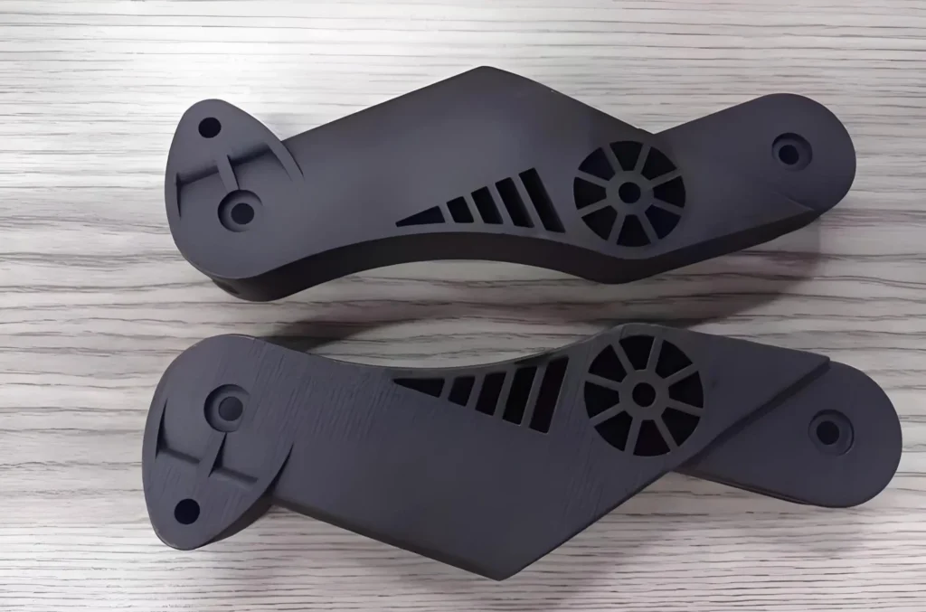
2. End-Use Production Parts:
This is where MJF truly shines and distinguishes itself from many other 3D printing technologies. It is not just a prototyping tool; it is a legitimate manufacturing solution.
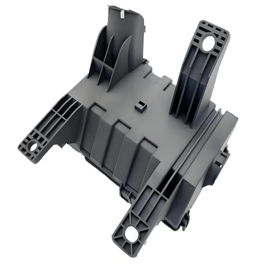
① Automotive Components:
The automotive industry leverages MJF for both prototyping and the production of non-critical interior, exterior, and under-the-hood components.
- Examples: Brackets, clips, fluid housings, dashboard components, custom trim pieces, and ducting.
- Benefits: The chemical resistance of PA 12 to oils and fluids, its durability, and the ability to produce complex, lightweight structures are key advantages.
② Medical and Healthcare Devices:
MJF materials like PA 12 are biocompatible (certified USP Class I-VI and US FDA guidance for Intact Skin Surface Devices) and can be sterilized, making them suitable for a wide range of medical applications.
- Examples: Surgical guides, orthopedic models, custom orthotics and prosthetics, medical device housings, and lab equipment.
- Benefits: Ability to create patient-specific parts, complex internal channels, and lightweight designs with excellent detail.
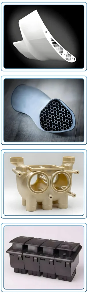
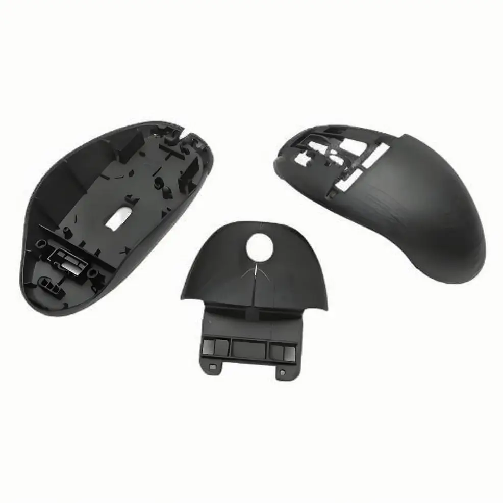
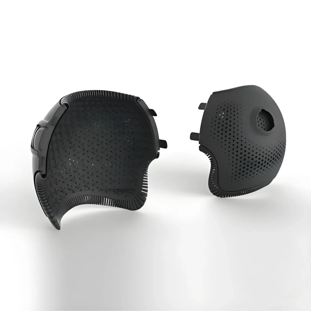
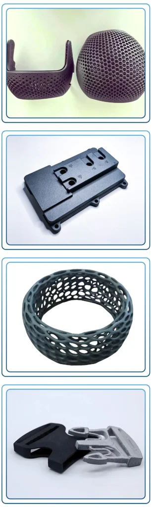
③ Consumer Goods and Electronics:
MJF is used to produce durable housings, enclosures, and internal components for a variety of consumer products.
- Examples: Drone bodies, custom electronic enclosures, headphone components, and protective casings.
- Benefits: Excellent surface finish (especially after post-processing), high detail, and the strength to withstand drops and daily use.
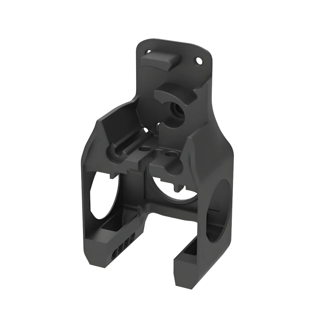
④ Industrial Jigs, Fixtures, and Tooling:
Manufacturing floors benefit immensely from MJF’s ability to quickly produce custom tooling.
- Examples: Assembly jigs, check gauges, drilling guides, and end-of-arm tooling for robotics.
- Benefits: Replacing heavy, expensive, and slow-to-produce metal tooling with lightweight, ergonomic, and cost-effective 3D printed alternatives improves production line efficiency and operator safety.
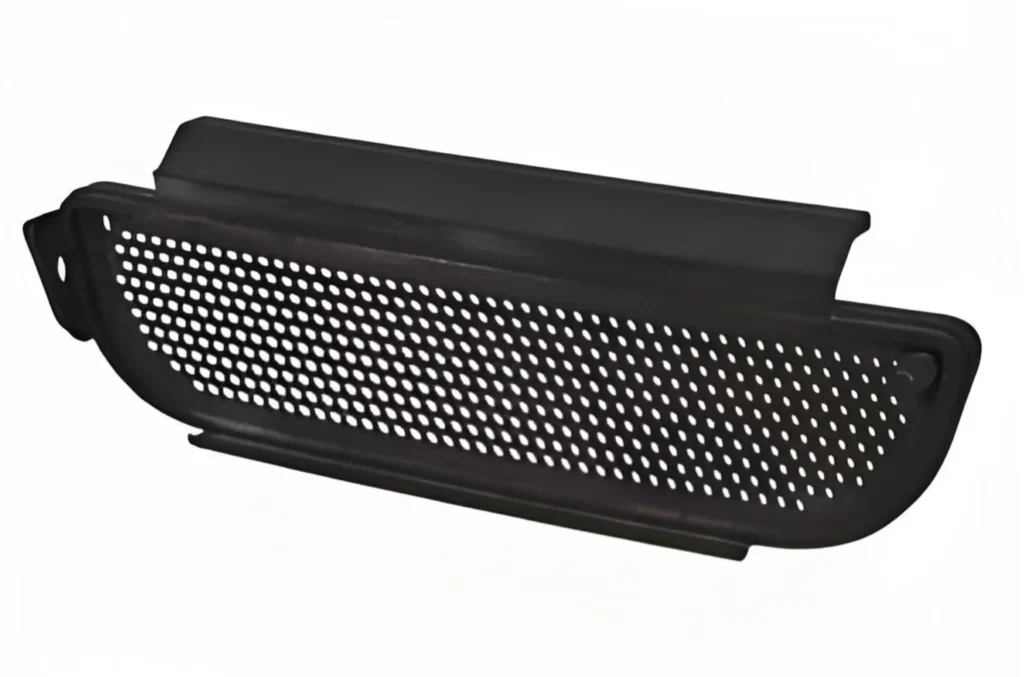
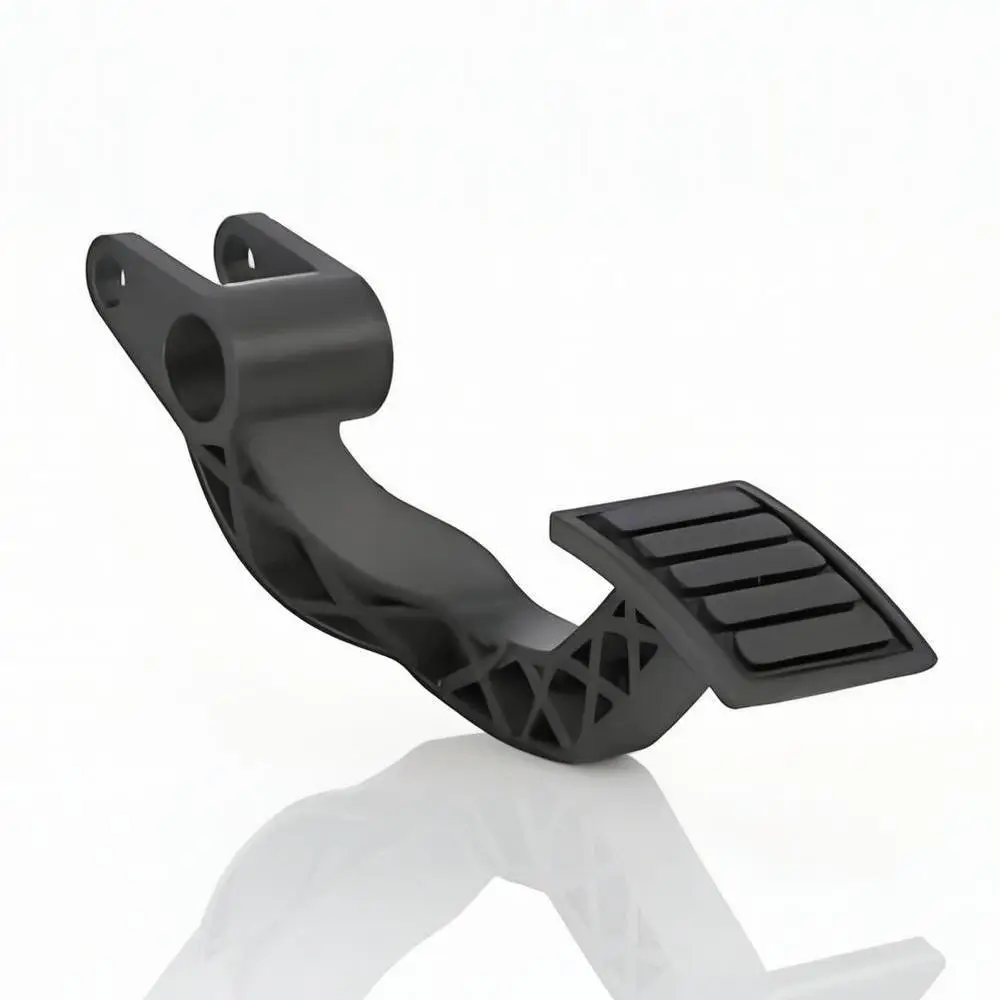
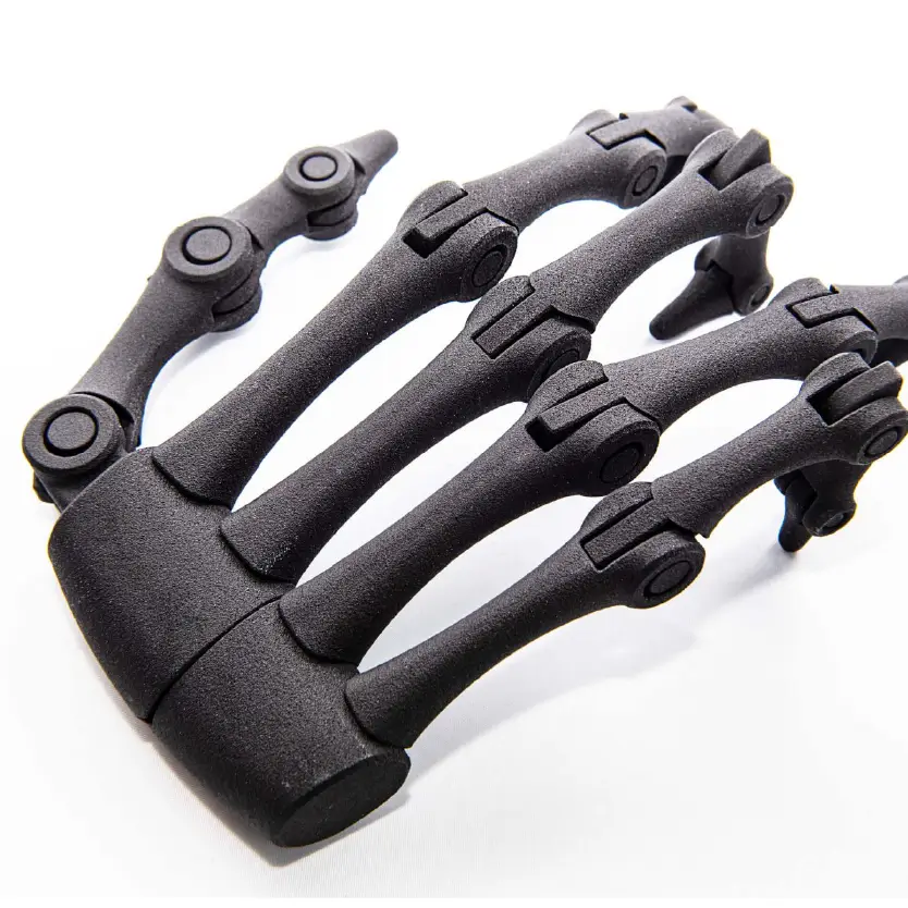
3. Complex Geometries and Lattice Structures:
Because MJF does not require support structures, it unlocks unprecedented design freedom. This is particularly valuable for applications that benefit from geometric complexity.
- Lattice Structures: Engineers can design parts with complex internal lattice structures to reduce weight and material usage while maintaining structural integrity. This is critical in aerospace and high-performance automotive applications.
- Part Consolidation: Multiple individual components of an assembly can be redesigned and printed as a single, complex part. This reduces assembly time, eliminates potential points of failure, and simplifies the supply chain.
Is MJF Suitable for Both Prototyping and Production?
Absolutely. One of the most compelling value propositions of Multi Jet Fusion is its dual capability, serving as a powerful tool for both the initial stages of product development and the final stages of manufacturing.
1. MJF for Rapid Prototyping:
MJF has emerged as a superior choice for creating high-quality functional prototypes.
- Speed: The area-wide printing process allows MJF to produce prototypes significantly faster than technologies like FDM or SLS, especially when the build volume is packed with multiple parts. A full build of prototypes can often be completed overnight.
- Functional Parity: MJF parts exhibit excellent, near-isotropic mechanical properties. This means a prototype’s strength and behavior are highly consistent regardless of its orientation in the build chamber. This predictability is crucial for functional testing, as the prototype behaves much like an injection-molded part would.
- Material Properties: Prototypes made from PA 12 or PA 11 are not just for visual assessment. They are tough, durable, and chemically resistant, allowing for real-world testing scenarios that would destroy prototypes from other technologies.
2. MJF for Serial Production:
MJF was engineered from the ground up with production in mind. Several factors make it a viable and often superior alternative to traditional manufacturing for certain applications.
- Economic Scalability: The cost per part with MJF is highly competitive, particularly for low-to-medium volume runs (from hundreds to thousands of units). The high speed, ability to nest parts densely in the build volume, and high powder reusability rate all contribute to favorable economics that challenge injection molding for these quantities.
- Consistency and Repeatability: MJF printers offer exceptional process control, resulting in high dimensional accuracy and part-to-part repeatability. This ensures that the 1,000th part is virtually identical to the first, a non-negotiable requirement for production environments.
- Supply Chain Agility: MJF enables on-demand manufacturing and digital inventory. Instead of warehousing physical parts, companies can store digital files and print parts as needed. This reduces storage costs, minimizes waste from obsolete stock, and allows for localized production, shortening lead times.
- Mass Customization: MJF makes it economically feasible to produce customized or personalized products at scale. Since there is no tooling, each part in a build can be unique without incurring additional costs.
3. The Bridge Between: From Prototype to Production with a Single Technology:
Using MJF for both prototyping and production creates a seamless transition. The prototype that was tested and validated is made from the exact same material and process as the final production part. This eliminates the risks and re-validation steps that often occur when switching from a prototyping technology (e.g., FDM) to a production technology (e.g., injection molding). This continuity de-risks the product development process and significantly accelerates time-to-market.
What Materials Are Commonly Used in MJF 3D Printing?
While the material selection for MJF is more curated than for other technologies like FDM, the available materials are highly engineered for performance and cover a wide range of industrial applications. The portfolio is continually expanding, but the primary materials are robust thermoplastics.
1. Polyamides (Nylons):
Nylons are the cornerstone of MJF printing, known for their excellent balance of strength, flexibility, and thermal/chemical resistance.
① PA 12 (The Workhorse Material):
HP 3D High Reusability PA 12 is the most common and versatile material for MJF. It’s a robust thermoplastic with excellent all-around properties.
Properties and Benefits:
- High Strength and Stiffness: Provides robust, durable parts.
- Good Chemical Resistance: Resistant to oils, greases, aliphatic hydrocarbons, and alkalis.
- Excellent Detail Resolution: Capable of producing fine features and sharp edges.
- Biocompatibility: Certified for medical applications involving skin contact.
- High Reusability: Industry-leading powder refresh rates (around 80% recycled to 20% virgin powder) make it cost-effective and more sustainable.
Common Uses: Functional prototypes, production jigs and fixtures, medical devices, automotive components, and complex assemblies. It is the go-to material for the majority of MJF applications.
② PA 11 (The Bio-Based Alternative):
HP 3D High Reusability PA 11 is produced from a renewable resource (castor oil), making it a more environmentally friendly choice. It offers different mechanical properties compared to PA 12.
Properties and Benefits:
- Superior Ductility and Impact Resistance: PA 11 is less brittle than PA 12 and offers higher elongation at break. This makes it ideal for parts that need to bend without breaking, such as snap-fits, living hinges, and components subject to impact.
- Enhanced Isotropic Properties: It exhibits even more consistent mechanical properties across all axes.
- Bio-Based: Offers a more sustainable material option.
Common Uses: Prosthetics, sports equipment, drone components, and any application requiring high toughness and fatigue resistance.
③ Glass-Filled PA 12 (PA 12 GB):
HP 3D High Reusability PA 12 with Glass Beads (GB) is a composite material containing 40% glass bead filler.
Properties and Benefits:
- Increased Stiffness and Dimensional Stability: The glass beads significantly increase the material’s rigidity and reduce its tendency to warp, making it ideal for parts that require high stiffness and must hold tight tolerances under load or temperature variations.
- Enhanced Wear Resistance: Offers better resistance to abrasive wear.
Common Uses: Housings, enclosures, fixtures, and tooling that require long-term stability and stiffness. It’s not suitable for parts requiring high impact strength or flexibility.
2. Thermoplastic Polyurethane (TPU):
Materials like BASF Ultrasint® TPU01 are available for MJF, enabling the production of flexible, rubber-like parts.
Properties and Benefits:
- Flexibility and Elasticity: Offers excellent rebound and tear resistance. It can be stretched and compressed repeatedly without permanent deformation.
- High Wear and Abrasion Resistance: Extremely durable for applications involving friction.
- Good Shock Absorption: Ideal for cushioning and dampening vibrations.
Common Uses: Seals, gaskets, hoses, bellows, grippers, wheels, and protective lattice structures for athletic gear or footwear.

How Does MJF Compare to Other 3D Printing Technologies?
Choosing the right 3D printing technology depends on the specific requirements of the application, such as speed, material properties, cost, and desired detail level. Here’s how MJF stacks up against other common industrial technologies.
1. MJF vs. Selective Laser Sintering (SLS):
SLS is the closest technology to MJF, as both are powder bed fusion processes. However, key differences determine which is better for a given job.
① Similarities:
- Both use thermoplastic powders (most commonly Nylon 12).
- Both are self-supporting, eliminating the need for dedicated support structures.
- Both produce strong, functional parts suitable for end-use applications.
② Key Differences:
- Fusion Method & Speed: SLS uses a single high-power laser to trace the part’s geometry point-by-point. MJF uses an inkjet array and an infrared lamp to fuse an entire layer at once. This makes MJF significantly faster (up to 10 times in some cases), especially for builds with many small parts or large cross-sectional areas.
- Detail and Surface Finish: The detailing agent in MJF provides better thermal control at the part’s boundary, typically resulting in sharper details and a slightly smoother surface finish compared to SLS.
- Material Reusability: MJF boasts a higher powder refresh rate (typically 80% recycled), whereas SLS often requires a 50/50 mix of recycled and virgin powder. This makes MJF more cost-effective and sustainable in terms of material consumption.
- Part Properties: MJF parts are generally more isotropic and have higher tensile strength and density than their SLS counterparts, making them mechanically superior.
③ When to Choose MJF over SLS?
Choose MJF for higher volume production runs, applications where speed is critical, parts requiring the best possible mechanical performance and fine details, and when cost per part is a primary driver.
SLS 3D Printing
2. MJF vs. Fused Deposition Modeling (FDM):
FDM is an extrusion-based technology that builds parts by depositing a molten filament layer by layer.
① Key Differences:
- Mechanical Properties (Isotropy): FDM parts are anisotropic, meaning they are significantly weaker in the Z-axis (between layers) than in the XY-plane. MJF parts are nearly isotropic, with strength being highly consistent in all directions. This makes MJF far superior for functional parts that will be under load.
- Surface Finish and Detail: MJF produces parts with a fine, granular texture and much higher feature resolution. FDM parts have visible layer lines and struggle with fine details and complex geometries without significant support structures.
- Design Freedom: The self-supporting nature of the MJF powder bed allows for the creation of extremely complex geometries, internal channels, and nested assemblies that are impossible or impractical to print with FDM due to its reliance on support structures.
- Speed & Scalability: For a single small part, FDM might be faster. For producing multiple parts at once, MJF is vastly superior due to its ability to nest parts and its area-wide printing process.
② When to Choose MJF over FDM?
Choose MJF when mechanical performance, dimensional accuracy, complex geometry, and a professional surface finish are required. FDM is better suited for low-cost initial concept models, simple geometries, and applications where anisotropic properties are acceptable.
FDM 3D Printing
3. MJF vs. Stereolithography (SLA):
SLA is a vat photopolymerization technology that uses a UV laser to cure liquid photopolymer resin layer by layer.
① Key Differences:
- Material Properties and Durability: SLA resins, while offering incredible detail, are generally more brittle and less durable than the engineering-grade thermoplastics used in MJF. MJF parts (like PA 12) are tough, flexible, and suitable for demanding functional applications. SLA parts are better for visual models and applications where high stiffness is needed but impact strength is not.
- Surface Finish: SLA produces the smoothest surface finish of any 3D printing technology, making it ideal for aesthetic prototypes, presentation models, and patterns for casting. Raw MJF parts have a granular texture, though this can be improved with post-processing.
- Application Focus: MJF is geared towards functional prototypes and production parts. SLA is the gold standard for high-detail visual models, form-fit prototypes, and casting patterns.
- Cost: For functional parts, MJF is generally more cost-effective, especially at scale.
② When to Choose MJF over SLA?
Choose MJF for any application requiring durability, impact strength, chemical resistance, and good mechanical properties for real-world use. Choose SLA when the highest priority is an ultra-smooth, injection-mold-like surface finish for visual purposes or for creating master patterns.
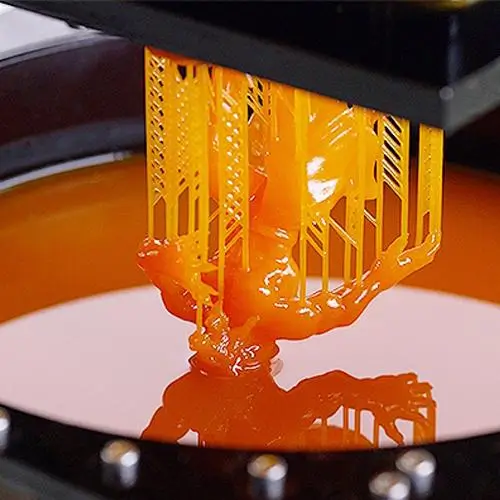
SLA 3D Printing
Multi Jet Fusion (MJF) 3D Printing
Learn how Multi Jet Fusion (MJF) 3D printing works, its key advantages, compatible materials, and why it’s ideal for functional prototypes and end-use parts.
Resources for The Complete Guide to Multi Jet Fusion (MJF) 3D Printing
What Are the Key Advantages of Using MJF?
Multi Jet Fusion offers a compelling set of benefits that make it a leading choice for modern manufacturing.
1. Exceptional Speed and Productivity:
The single-pass, area-wide fusing process is the core of MJF's speed. By processing an entire layer at once, it can produce parts at speeds up to 10 times faster than competing technologies like SLS and FDM, drastically reducing lead times for both prototypes and production runs.
2. Superior Mechanical Properties and Isotropy:
MJF parts exhibit best-in-class isotropic properties, meaning they have nearly uniform strength and durability in the X, Y, and Z directions. This is a critical advantage over FDM and even an improvement over SLS, resulting in predictable, reliable parts that perform like their injection-molded counterparts.
3. High Accuracy and Fine Detail Resolution:
The combination of a high-resolution inkjet printhead (1200 DPI) and the unique detailing agent allows MJF to produce parts with fine feature definition (down to 0.5mm), sharp edges, and excellent dimensional accuracy.
4. Cost-Effectiveness for Small to Medium Batches:
MJF's high speed, efficient part nesting (filling the build volume in 3D), and industry-leading powder reusability rate combine to deliver a low cost per part. This makes it an economically viable manufacturing solution for production runs that are too small for cost-effective injection molding.
5. Design Freedom (No Support Structures Needed):
Like SLS, MJF parts are supported by the bed of unfused powder they are printed in. This eliminates the need for generating and post-processing support structures, enabling the creation of intricate internal features, complex geometries, and ready-to-use moving assemblies printed in a single piece.
6. High Material Reusability:
With powder refresh rates as low as 20% virgin material per build, MJF minimizes waste and reduces material costs. This makes it a more sustainable and economical choice compared to other powder bed processes with lower recyclability rates.
What Are the Limitations of Multi Jet Fusion?
While MJF is a powerful technology, it’s important to understand its limitations to determine if it’s the right fit for your project.
1. Limited Material Selection:
Compared to technologies like FDM, the portfolio of materials for MJF is currently smaller and primarily focused on nylons and TPU. While the available materials are highly capable, projects requiring specific materials like ABS, PC, or high-temperature ULTEM may need to look to other processes.
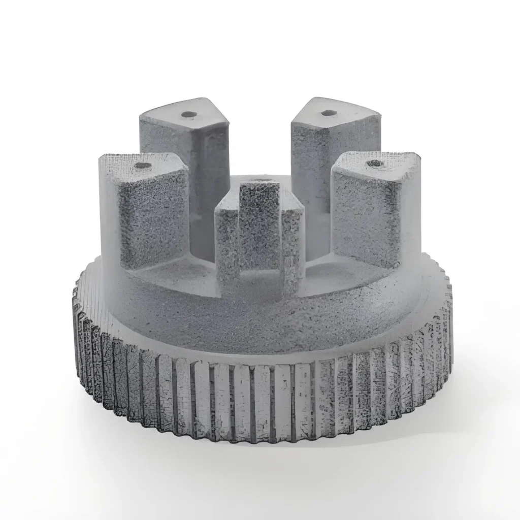
2. Inherent Surface Finish and Color:
Raw MJF parts come in a consistent gray or black color (depending on the material) and have a slightly grainy, matte surface finish similar to a sugar cube. While this can be significantly improved with post-processing (like dyeing or vapor smoothing), it does not match the out-of-the-box smoothness of SLA or injection molding.
3. Cooling Time Requirement:
A significant portion of the MJF workflow is the controlled cooling cycle. The build unit must cool for a period roughly equal to the print time to prevent warping and ensure optimal part properties. This means that even if a print job finishes in 12 hours, the parts won't be ready for extraction and cleaning for another 12 hours, impacting the true "time-to-part."
4. Not Ideal for Very Large Parts:
The build volume of MJF machines is generous but finite (e.g., around 380 x 284 x 380 mm for HP's 5200 series). For parts that exceed these dimensions, they must be broken into smaller pieces and assembled after printing, or a different technology with a larger build platform (like large-format FDM or SLA) must be used.
5. Higher Initial Equipment Cost:
For companies looking to bring the technology in-house, the initial investment in an industrial MJF system (including the printer, processing station, and materials) is substantial. This is why many businesses choose to leverage the technology through a service provider like us.
What Are the Design Guidelines for MJF 3D Printing?
Designing parts specifically for MJF will ensure you achieve the best possible results in terms of quality, accuracy, and strength. Adhering to these guidelines will minimize print failures and optimize your parts for the process.
1. Key Design Considerations:
① Wall Thickness:
- Minimum Recommended: 0.5 mm for very small features. For robust parts, a minimum wall thickness of 1 mm is highly recommended.
- Maximum: Avoid overly thick, solid sections, as they can accumulate excess heat, leading to potential inaccuracies or warping. Hollow out large sections where possible.
② Hole Sizes and Diameters:
- Minimum: For vertical holes (perpendicular to the layers), a minimum diameter of 0.5 mm is possible.
- Best Practice: Design holes slightly larger than intended to account for minor shrinkage. For threaded holes, it’s best to print them undersized and then tap them in post-processing for optimal thread quality.
③ Feature Size and Resolution:
- Embossed/Debossed Details: For text or surface details, ensure they have a minimum height/depth of 0.5 mm and a line thickness of at least 0.5 mm to be clearly legible.
- Smallest Features: MJF can resolve features down to 0.5 mm. Anything smaller may not print successfully.
④ Clearances for Assemblies:
- For parts that need to fit or move together (e.g., snap-fits, hinges, interlocking parts), a minimum clearance of 0.4 mm is recommended. For parts requiring a looser fit, increase this to 0.6 mm or more.
⑤ Warping and Large Flat Surfaces:
- Very large, flat, and thin surfaces (like a large baseplate) can be prone to warping during the cooling process.
- Mitigation: Add ribs or gussets to increase stiffness, or orient the part at an angle in the build if possible. Breaking up large flat areas with subtle texturing can also help.
⑥ Hollowing and Escape Holes:
- To save material, reduce weight, and lower cost, it is highly recommended to hollow out large, solid models.
- Escape Holes: If a part is hollowed, you must include at least two escape holes to allow the unfused powder to be removed after printing. The minimum recommended diameter for an escape hole is 2 mm, but larger (4-5 mm) is better for easier cleaning.
2. A Summary Table of Design Recommendations:
| Feature | Recommended Minimum | Best Practice |
|---|---|---|
| Wall Thickness | 0.5 mm | 1.0 mm or greater |
| Hole Diameter | 0.5 mm | 1.0 mm (tap for threads) |
| Clearance (Assemblies) | 0.4 mm | 0.6 mm for looser fits |
| Engraved/Embossed Detail | 0.5 mm depth/height | 1.0 mm for high clarity |
| Escape Holes (for hollowing) | 2.0 mm diameter (2 holes) | 4.0 mm+ diameter |
What Post-Processing Options Are Available for MJF Parts?
Raw MJF parts are fully functional, but a range of post-processing options can be applied to enhance their aesthetics, surface finish, and specific functional properties.
1. Standard Post-Processing:
Powder Removal (Bead Blasting): This is a standard and required step for all MJF parts. After being extracted from the loose powder, parts are meticulously cleaned in a blasting cabinet using media like glass beads. This removes all residual powder, resulting in a clean, matte, slightly textured surface. This is the standard finish for MJF parts.
2. Aesthetic and Functional Enhancements:
① Dyeing:
This is the most common and cost-effective way to color MJF parts. Because the base material is porous, it readily accepts dye.
- Process: Parts are submerged in a hot dye bath, which penetrates the surface, providing a deep, rich, and durable color.
- Common Colors: Black is the most popular choice as it creates a very uniform, professional finish that hides any minor imperfections. Other colors like blue, red, green, and yellow are also available.
- Result: A scratch-resistant color that won’t chip or flake off.
② Vapor Smoothing:
This is a transformative post-processing technique that dramatically improves the surface finish.
- Process: The part is exposed to a vaporized solvent in a controlled chamber. The vapor melts the outer surface of the part at a microscopic level, smoothing out the grainy texture and sealing the surface.
- Result: A semi-glossy, smooth surface finish that closely resembles injection-molded plastic. It also improves elongation at break and makes the part watertight and easier to clean.
③ Painting and Coating:
For specific color requirements (e.g., Pantone matching) or special protective properties, MJF parts can be painted or coated.
- Process: Parts are typically primed first to create a uniform base, then painted with automotive-grade or other specialized paints. Coatings like Cerakote can be applied for enhanced hardness, wear resistance, and chemical resistance.
- Result: Unlimited color options and tailored surface properties.
④ Machining and Tapping:
For features requiring extremely high precision that 3D printing cannot achieve, MJF parts can be secondarily machined.
- Process: Critical surfaces can be milled or turned, and holes can be drilled and tapped to create strong, reliable threads for metal screws.
- Result: A hybrid part that combines the design freedom of MJF with the precision of traditional subtractive manufacturing.
Frequently Asked Questions About MJF 3D Printing
Lead times can vary based on part size, quantity, and required post-processing. However, due to the technology’s speed, standard lead times are often as short as 3-5 business days for parts with a standard bead-blasted finish.
MJF parts are exceptionally strong and durable, especially those made from PA 12 and PA 11. Their near-isotropic properties mean they are reliable under stress from any direction, making them suitable for demanding functional applications and end-use parts.
A raw, bead-blasted MJF part has a matte, gray finish with a slightly grainy texture, often compared to a sugar cube or very fine sandpaper. This finish can be dramatically improved with post-processing like vapor smoothing.
A raw MJF part has some microporosity and is not guaranteed to be watertight. However, applying a post-processing step like vapor smoothing seals the surface, making the part watertight and suitable for applications involving fluids.
Compared to many manufacturing methods, MJF has strong sustainability credentials. The high powder reusability rate (often 80% or more) significantly reduces material waste. Furthermore, producing parts on-demand eliminates the waste associated with overproduction and obsolete inventory common in traditional manufacturing.
Why Should You Choose Us for Your MJF 3D Printing Needs?
Our team has deep experience in Multi Jet Fusion (MJF) technology. From early-stage prototyping to final production, we provide design-for-manufacturing (DFM) guidance to ensure your parts are both functional and cost-effective.
We use advanced HP Jet Fusion printers to deliver high-resolution, dimensionally accurate, and repeatable parts. Whether you need a single prototype or a large production run, we have the capacity and precision to meet your needs.
We offer a selection of high-performance MJF materials, including PA 11, PA 12, PA 12 GB, and flexible TPU. All materials are carefully sourced to ensure mechanical strength, durability, and excellent surface finish.
With in-house production and streamlined workflows, we can deliver parts quickly—often within 3–7 days depending on complexity and volume—so your project never gets delayed.
From vapor smoothing and dyeing to post-machining and assembly, we offer a range of finishing services to help your MJF parts meet both functional and aesthetic requirements.
We serve clients worldwide with reliable logistics and English-speaking engineering support. Your questions will be answered within 12 hours—guaranteed.

Metal Insert Injection Molding: Design & Defect Prevention
Key Takeaways Metal insert injection molding integrates metal components directly into plastic parts during molding for superior mechanical bond strength. Insert design—knurling, undercuts, wall thickness—is the primary driver of pull-out

Top 5 Injection Molding Companies in Pakistan
Key Takeaways Pakistan has an active plastics manufacturing sector centered around Karachi and Lahore, primarily serving domestic consumer goods, packaging, and automotive aftermarket markets. Precision injection molding capability for export-grade

What Are Geometric Tolerances in Injection Molding
Your design file says ±0.1mm. Your molder quotes ±0.2mm. Your customer requires flatness within 0.05mm across the whole sealing surface. Three different numbers — none of them speak the same
Optimization Solutions Provided For Free
- Provide Design Feedback and Optimization Solutions
- Optimize Structure and Reduce Mold Costs
- Talk Directly With Engineers One-On-One

