 콘텐츠로 건너뛰기

작은 엔드밀(8~16mm)을 사용하여 보통의 이송 속도로 재고를 0.1~0.2mm까지 줄여, 캐비티 표면을 정제하면서 마무리 패스에 남길 작업량을 최소화합니다. 이 단계는 마무리 공구 경로가 따르는 정확한 기준면을 확립하는 데 중요합니다.
– CNC machining is the most time-intensive step, often requiring 80–400 hours of cutting time depending on part complexity and number of cavities.
– Mold flow analysis before cutting steel can prevent 70–80% of costly tooling modifications by identifying fill, cooling, and warpage issues in simulation.
– A production mold for a typical consumer product takes 4–6 weeks from design sign-off to first article inspection.
What Happens Before a Single Cut Is Made in Mold Manufacturing?
Before any metal is cut, mold manufacturing begins with a critical design review phase—analyzing the customer’s part design, selecting mold type and steel grade, performing mold flow simulation, and producing detailed 3D mold design data. In our factory, we spend roughly 20–30% of total mold lead time in this pre-machining phase, and it’s the most important investment we make.
The starting point is a Design for Manufacturability (DFM) review of the customer’s 3D part model. We check for minimum wall thickness (our rule: 1.0 mm minimum for most resins), consistent wall thickness to prevent warpage and sink marks, adequate draft angles (1°–3° minimum), undercut features requiring sliders or lifters, and gating locations that will fill the part without weld lines in critical areas.
After DFM sign-off, our mold designers use CAD software (typically CATIA or Solidworks with specialized mold design modules) to create the full mold assembly: cavity and core inserts, mold base, runner system, cooling channel layout, ejection system, and any side-action components. This design package typically runs 200–600 pages of engineering drawings and 3D data files.
How Does Mold Flow Analysis Improve the Mold Design?
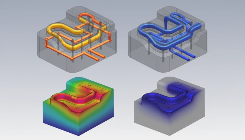
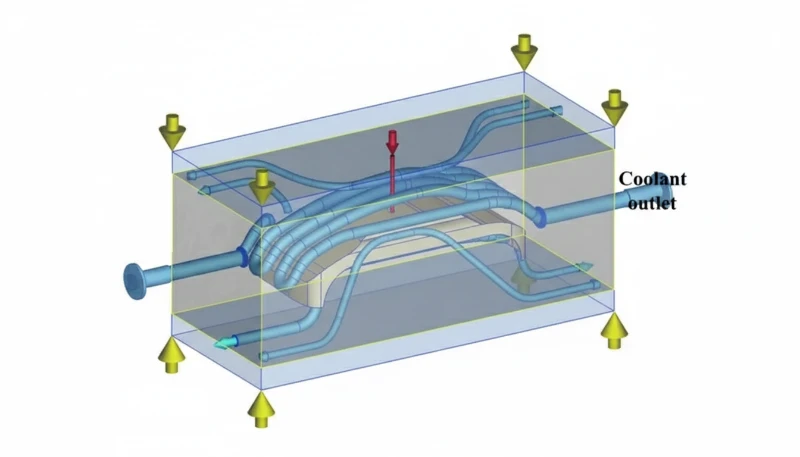
금형 흐름 분석1 improves mold design by simulating plastic fill, pack, and cooling stages before the mold is cut—identifying potential defects like weld lines, air traps, sink marks, and warpage before they become expensive steel modifications. We run mold flow on every production mold we build; it’s non-negotiable in our operation.
The simulation solves the coupled fluid dynamics and heat transfer equations for the specific resin, part geometry, proposed gate location, and cooling channel layout. Outputs include fill time maps showing how the melt front progresses, pressure distribution at fill end, temperature maps identifying hot spots in the tool, weld line positions, and predicted warpage after ejection and cooling.
We’ve seen mold flow analysis save $20,000–$80,000 per project by identifying problems before they’re machined in. A common example: a customer proposes a single center gate for a rectangular 400×300 mm part. Simulation reveals that single-gate filling creates weld lines across two functional snap-fit features. We redesign to a two-gate hot runner system—adding $3,000 to the mold cost but eliminating what would have been $15,000 in gate modifications and weeks of delay after the mold was already built.

“Experienced mold makers don’t need simulation—their experience is sufficient to design a good mold.”False
Even 30-year veterans cannot visualize three-dimensional polymer flow dynamics with thermal gradients in complex multi-cavity tools. Simulation software processes thousands of variables simultaneously. In our factory, we’ve watched master moldmakers’ intuitive designs fail simulation validation repeatedly—simulation is not optional at modern quality standards.
“Mold flow simulation can predict warpage within 10–15% accuracy, making it a reliable pre-build validation tool.”True
Modern simulation software (Moldflow, Moldex3D) predicts warpage, fill balance, and sink mark risk with 10–15% accuracy when given accurate material rheology data. This accuracy is sufficient to make valid design decisions and avoid the majority of post-build tooling modifications.
What Steel Is Used and How Is It Prepared for Machining?
Injection mold steel is selected based on required production volume, plastic material, and surface finish, with P20, H13, S136, and NAK80 being the most commonly used grades—then cut to rough block dimensions by the steel supplier, stress-relieved, and inspected before machining begins. In our factory, we’ve learned that steel quality is never a place to cut costs; substandard blocks with inclusions or internal stress cause catastrophic cracking during EDM operations.
For a typical P20 mold base, we receive pre-hardened blocks at 28–32 HRC from our certified steel suppliers, already cut to within 5–10 mm of final block dimensions. Before any machining begins, we perform ultrasonic testing on blocks thicker than 80 mm to check for internal voids or segregation—defects that won’t appear until a tool cavity is cut and loaded in production.
For H13 and S136 molds that will be hardened after roughing, we rough-cut all features with 0.3–0.5 mm stock remaining on all surfaces, send the block to heat treatment (hardening to 50–54 HRC for H13, 48–52 HRC for S136), then finish-machine to final dimensions. This sequencing is critical: you cannot hardening after finishing—the thermal distortion from quenching would destroy the precision you spent dozens of hours achieving.
| 강철 등급 | 경도(HRC) | Shot Life | Best Application |
|---|---|---|---|
| P20 (pre-hardened) | 28–32 HRC | 300K–500K shots | General production, ABS, PP, PE |
| H13 (heat-treated) | 44–48 HRC | 1M–2M shots | High volume, glass-filled, PC |
| S136 (stainless) | 48–52 HRC | 1M–3M shots | Medical, optical, PVC, corrosive resins |
| NAK80 (pre-hardened) | 37–43 HRC | 500K–800K shots | High-polish, transparent parts |
| 7075 알루미늄 | Brinell 150 | 5K–50K shots | Prototype molds, fast turnaround |
How Is CNC Machining Used to Create Mold Cavities and Cores?
CNC machining creates mold cavities and cores by removing material from steel blocks using multi-axis milling centers with carbide tooling, following the 3D mold design data in multiple sequential operations from rough material removal to semi-finishing to fine finishing passes. In our factory, CNC machining accounts for 40–60% of total mold manufacturing time and requires the most skilled programming and setup.
The machining sequence for a typical cavity block proceeds in three phases. Roughing uses large end mills (20–32 mm diameter) at high feed rates to remove the bulk of material—leaving 0.5–1.0 mm stock on all surfaces. We use high-speed roughing toolpaths that maintain consistent chip load regardless of geometry changes, protecting the machine spindle and extending cutter life.
Semi-finishing reduces stock to 0.1–0.2 mm using smaller end mills (8–16 mm) at moderate feed rates, refining the cavity surface while minimizing the amount of work left for finish passes. This step is critical for establishing accurate reference surfaces that finishing toolpaths follow.
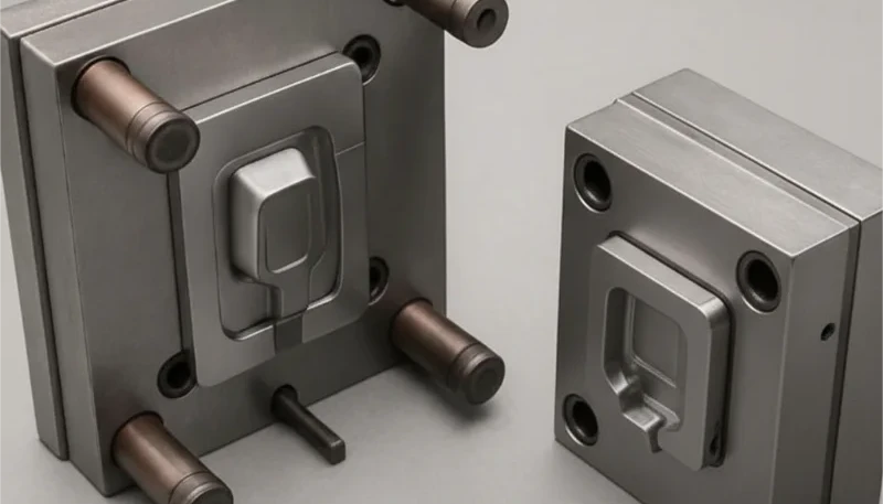
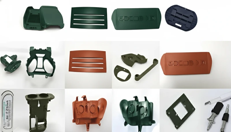
정밀 사출 금형 툴링으로 가공된 코어 및 캐비티 인서트가 적용된 다중 캐비티 금형을 보여줍니다 use ball-nose end mills as small as 0.5–1.0 mm diameter for detailed features, running at 20,000–40,000 RPM spindle speeds with step-over distances of 0.05–0.1 mm to achieve Ra 0.4–0.8 µm surface roughness before polishing. For a complex A-side cavity with a 300×250 mm surface area, finishing alone can take 16–40 hours of CNC time.
What Role Does EDM Play in Making Injection Molds?
EDM (Electrical Discharge Machining) creates sharp internal corners, deep ribs, fine text engravings, and complex geometry that CNC milling cannot reach—by eroding metal with controlled electrical sparks between an electrode and the steel workpiece without mechanical contact. We use EDM for 60–80% of our production molds, particularly for features like sharp rib bottoms under 0.3 mm radius and deep slots with aspect ratios above 5:1.
There are two primary EDM processes in mold making. Sinker EDM (also called die-sinking or ram EDM) uses a shaped graphite or copper electrode that erodes the steel to create a negative mirror image of itself. We machine custom electrodes on dedicated graphite CNC machines, then program sequences of roughing and finishing spark conditions to achieve the final surface quality. Tolerances of ±0.005 mm are routinely achieved.
Wire EDM uses a continuously moving brass wire (0.1–0.3 mm diameter) to cut precise 2D profiles through the full thickness of a block. We use wire EDM for ejector pin holes, core pin holes, and cutting precision through-slots that would require multiple CNC setups to achieve the same straightness.
The main limitation of EDM is speed—it’s 5–10× slower than CNC milling for material removal. We always machine as much as possible with CNC and reserve EDM for features that truly require it. Strategic EDM placement is one of the key skills that separates efficient mold shops from slow ones.
“Wire EDM should be used for all mold features because it’s the most precise machining method.”False
Wire EDM is limited to through-cuts—it cannot produce blind pockets, curved 3D surfaces, or features that don’t pass fully through the workpiece. CNC milling handles 3D surfaces, while EDM (sinker) handles blind features that CNC cannot reach. Optimal molds use each process for what it does best.
“Combining CNC and EDM in sequence produces molds with tighter tolerances than either process alone.”True
CNC roughing and semi-finishing remove material efficiently to within 0.1 mm of final dimensions, then EDM finishes critical features to ±0.005 mm. The two processes complement each other: CNC provides speed and 3D surface capability, while EDM provides extreme precision and sharp-corner geometry.
How Is the Mold Surface Finished and Polished?
Mold surface finishing progresses from stone grinding to progressively finer diamond polishing compounds, ultimately achieving mirror-like surfaces for optical and cosmetic applications, or specific texture finishes (VDI/Mold-Tech) for functional parts. Polishing is the most labor-intensive single step in mold making—and the hardest to automate. In our factory, our polishing team is among the most specialized; mirror-finish polishing is a skill that takes years to master.
The polishing sequence starts with grinding stones (600 grit → 800 grit) to remove EDM recast layer and machining tool marks. We then progress through diamond pastes: 6 µm → 3 µm → 1 µm → 0.25 µm for SPI B-2 standard (commercial polish); continuing to 0.1 µm diamond and 50 nm oxide polishing compound for SPI A-1 mirror finish.
For textured surfaces (SPI C or D standards, or specific VDI texture patterns for rubber-touch finishes), we skip fine polishing and instead chemically etch the steel after all machining is complete. Texture depth determines required additional draft angle: every 0.025 mm of texture depth requires an additional 1° of 구배 각도2 per side. We ensure draft angles are approved before any texturing is applied—removing texture from an already-textured surface requires significant rework.
What Happens During Mold Trial and First Article Inspection?
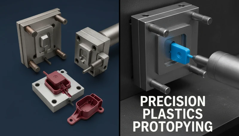
Mold trial (also called “T1 trial”) is the first production test of the finished mold—running it on the target injection machine with the specified resin to evaluate fill, surface quality, dimensional accuracy, and ejection function before the mold is shipped to the customer. In our factory, T1 trials are the most intense days of the mold-making process; every defect found is an opportunity to improve before the mold reaches the customer’s facility.
Before the first shot, we dry the specified resin to manufacturer requirements, set initial process parameters based on material data sheets (melt temperature, mold temperature, injection speed, and cooling time), and install the mold with tooling clamps verified to the machine platen specification. We run the first shots with slow injection speed and monitor fill on a shot-by-shot basis, increasing speed incrementally until the part fills 95%, then adjusting holding pressure to complete pack.
First Article Inspection (FAI) documents that every dimension on the customer’s drawing is within tolerance. We use a CMM (Coordinate Measuring Machine) for all critical dimensions, reporting actual versus nominal for each measurement point. Typical FAI reports for automotive or medical parts contain 50–200 measured dimensions with tolerances as tight as ±0.01 mm for critical features.
After T1, most molds require minor corrections: adjusting gate size for fill balance, adding vent slots where air traps cause short shots, polishing ejector pin witness marks, or steel-safe dimensional corrections (trimming steel to open dimensions slightly). We build “steel-safe” on all dimensions that could require adjustment—meaning we machine dimensions slightly small on cores and large on cavities, allowing material removal to correct any dimension that’s out of tolerance.

Frequently Asked Questions About How Injection Molds Are Made
Q: How long does it take to make an injection mold from start to finish?
A: Prototype molds in aluminum take 2–3 weeks. Single-cavity production molds in P20 typically take 4–5 weeks. Complex multi-cavity or hot-runner molds take 6–10 weeks. Lead time is primarily driven by CNC machining hours, heat treatment turnaround, and polishing time—not waiting.
Q: Can I make changes to my part design after the mold is built?
A: Minor dimensional changes can often be made by adding or removing steel (within steel-safe margins). Adding material to the mold reduces part dimensions; removing steel increases them. Significant redesigns—changing gate location, adding features, changing wall thickness—typically require new inserts or sections of the mold to be re-machined.
Q: What is “steel-safe” and why does it matter?
A: Steel-safe means machining dimensions conservatively—cores slightly small, cavities slightly large—so that if parts come out of tolerance after the first trial, steel can be removed (not added) to correct the dimension. It’s always possible to remove steel; adding it requires expensive welding and re-machining. We apply steel-safe principles on every dimension with an expected tolerance tighter than ±0.1 mm.
Q: How much does a mold modification cost after it’s built?
A: Minor modifications (polishing, adjusting vent depth, gate trimming) cost $200–$1,500. Adding a new slider or lifter for an undercut feature not anticipated in the original design costs $3,000–$12,000. A major cavity re-cut costs $8,000–$30,000 and adds 2–4 weeks. These costs reinforce why thorough DFM review before cutting steel is essential.
Q: Can injection molds be 3D printed?
A: Yes, for very low volumes (under 100 shots) or for concept validation. Metal 3D printed (DMLS/SLM) molds in tool steel are increasingly viable for prototype molds, offering conformal cooling channels3 that traditional drilling cannot achieve. For production volumes, traditionally machined steel molds remain more economical and reliable.
Q: What is the difference between a mold maker and a mold builder?
A: The terms are often used interchangeably, but technically: a mold designer creates the 3D design data; a mold maker machines and assembles the physical tool; a mold builder may refer to the full company that handles design, machining, and trials. In our factory, we have all three capabilities under one roof, which eliminates communication delays between design and production teams.
요약
Making an injection mold is one of manufacturing’s most demanding precision processes. Every stage—from the DFM review that catches design problems before they become tooling problems, to the simulation that validates cooling and fill balance before steel is cut, to the CMM inspection that verifies every dimension against the customer’s drawing—requires deep technical expertise and rigorous process discipline.
In our factory, we’ve built thousands of molds over the years, and the pattern is consistent: molds built with thorough pre-machining analysis, quality steel, disciplined sequencing of CNC and EDM operations, and careful trial management deliver excellent first-article results with minimal modification cycles. Shortcuts in any of these steps invariably create delays and costs that far exceed the savings.
If you’re planning a new injection molded product, the most important thing you can do is engage your mold maker early—before finalizing your part design. A good mold maker can save you weeks and thousands of dollars by catching moldability issues in the design phase rather than in the tooling phase.
-
Mold flow analysis is a computer simulation technique using finite element methods to model the flow, cooling, and solidification of molten plastic in a mold cavity, predicting defects such as weld lines, sink marks, and warpage before the physical mold is manufactured. ↩
-
Draft angle is the taper angle applied to vertical part walls perpendicular to the mold parting line, enabling the solidified part to release from the mold without scuffing. Standard injection molded parts require 1°–2° per side; textured surfaces require additional draft at 1° per 0.025 mm of texture depth. ↩
-
Conformal cooling channels are mold cooling channels that follow the contour of the cavity surface at a uniform distance, achieving more uniform cooling than straight-drilled channels. They are typically produced by metal additive manufacturing (DMLS) and can reduce cycle time by 15–40% for complex geometries. ↩


