 コンテンツへスキップ

Why Does Mold Precision Matter More Than Machine Precision?
Mold precision is the main limit on molded part accuracy. A precise machine cannot compensate for a cavity, core, shutoff, or cooling layout that was designed or machined incorrectly. In our factory, we have seen expensive machines produce unstable dimensions when mold quality was treated as secondary, because the tool defines the geometry every shot must follow. Understanding the 射出成形 process shows exactly where precision is locked in—and where it can be lost.
射出成形金型もし部品が現在公差を満たしていない場合、診断アプローチは体系的です:まず金型寸法を元の設計と照合(金型は正しいか?)、次に収縮補正の精度を確認(金型設計は正しいか?)、そしてプロセスSPCデータを分析(プロセスは安定しているか?)します。私たちの経験では、この3段階診断により、精度不良の根本原因の90%以内に特定できます。詳細は shrinkage compensation1 and anisotropy), and process consistency (injection pressure, melt temperature, and cooling time repeatability). Remove any one of these three, and dimensional control degrades.
The industry benchmark for precision injection molding is achieving tolerances conforming to DIN 16901 or ISO 20457 dimensional tolerance standards. For example, ISO 20457 Class M1 (highest precision) requires tolerances of ±0.05 mm on dimensions up to 50 mm. Achieving this level demands not just tight machining tolerances—it requires validated shrinkage factors, balanced cooling, and a statistically controlled production process (Cpk2 ≥ 1.67).
- Precision mold accuracy starts with cavity geometry, not machine settings.
- Validated shrinkage compensation and balanced cooling prevent most dimensional drift.
- CMM inspection, SPC, and controlled repair loops keep production dimensions stable after launch.
How Does Accurate Shrinkage Compensation Improve Dimensional Precision?
Shrinkage compensation is the cavity-size correction that offsets plastic contraction after cooling. Every thermoplastic shrinks as it changes from melt to solid, so the mold cavity must be sized larger than the final part by a controlled amount. In our operation, this decision is made before steel cutting and then verified through first sample measurement.
Nominal shrinkage rates are published by resin manufacturers—typically 0.4–0.7% for ABS, 1.0–2.5% for PP, 0.5–0.8% for PC, and 1.5–2.2% for PA 6/6. But published values are averages. Actual shrinkage in a specific mold depends on: wall thickness (thicker sections shrink more), gate distance (areas near the gate pack more and shrink less), holding pressure level, cooling rate, and glass fiber content (which reduces and anisotropizes shrinkage).
For precision parts, we never rely solely on published shrinkage values. We run mold flow analysis to predict location-specific shrinkage across the part, then validate with actual molding trials and adjust cavity dimensions based on measured part deviation. This empirical approach typically requires 1–2 dimensional correction cycles before achieving final approval.
| 素材 | Nominal Shrinkage | Variables Affecting Shrinkage | Precision Risk |
|---|---|---|---|
| ABS | 0.4–0.7% | Wall thickness, mold temp | 低い |
| PP (homopolymer) | 1.5–2.5% | Crystallinity, hold pressure | 高い |
| PC | 0.5–0.7% | Mold temp, wall thickness | 低い |
| PA 6/6 | 1.5–2.2% | Moisture, crystallinity, orientation | 高い |
| PA 6/6-GF30 | 0.4–0.8% | Fiber orientation, anisotropic | Medium (anisotropic) |
| POM (acetal) | 2.0–3.5% | Highly crystalline, large range | 非常に高い |
““Mold flow simulation predicts location-specific shrinkage with better accuracy than generic material datasheets.””真
Mold flow software calculates shrinkage at each element of the part geometry using validated material rheology models, accounting for local pressure, temperature, and cooling rate variation. This location-specific prediction typically achieves 70–80% of the accuracy needed—requiring only fine-tuning in dimensional correction cycles rather than complete redesign.
““Using the published shrinkage rate from the material datasheet is sufficient for precision mold design.””偽
Published shrinkage rates are average values that can vary ±30–50% from actual part shrinkage depending on wall thickness, hold pressure, cooling rate, and gate location. For parts requiring tolerances tighter than ±0.2 mm, mold flow simulation and empirical validation are essential—datasheet values alone are insufficient.
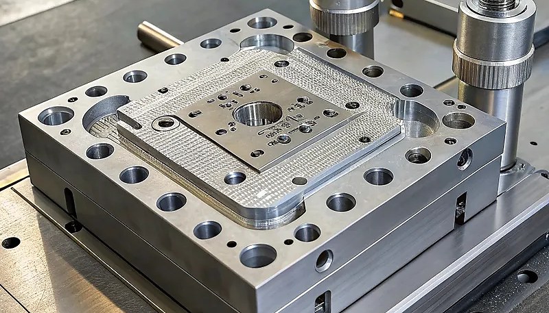
What Machining Practices Achieve the Tightest Mold Tolerances?
Tight mold tolerance is achieved through stable machining, measurement, and correction passes. The core requirement is not one perfect CNC cut, but a controlled loop of temperature stability, toolpath discipline, in-process probing, and final dimensional verification against the CAD model.
Our CNC machining approach for precision mold work uses several key practices. Thermal stabilization: the machine warms up for 30 minutes before cutting precision features. Spindle thermal growth is measured and compensated automatically. Steel workpieces are conditioned to room temperature (22°C) before precision cuts.
Chip load optimization for the specific steel hardness: we program higher cutting speeds (150–200 m/min) for P20 at 28–32 HRC and lower speeds (80–120 m/min) for H13 at 44–48 HRC, maintaining consistent chip thickness per tooth. Consistent chip load produces consistent cutting forces, which translates to consistent surface position accuracy.
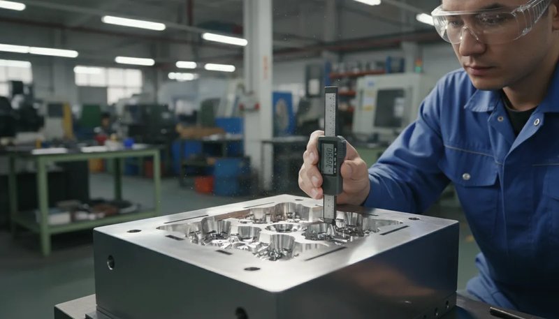
In-process measurement エンジニアが測定ツールを使用して射出成形金型の精度を検査し、キャビティの位置合わせと組み立て精度を確認しています
In our precision mold reviews, we combine in-house tooling, 8 senior engineers, and 10+ QC specialists before steel-safe release. The design team checks UG, SOLIDWORKS, MOLDFLOW, CAD outputs, and CMM3 inspection needs against machining, cooling, assembly, and inspection risks so dimensional accuracy is not left to final sampling alone.
How Does Cooling System Design Impact Part Dimensional Accuracy?
Cooling design is a major driver of dimensional accuracy because temperature gradients create uneven shrinkage. When one area of the part cools faster than another, warpage and dimension drift appear even if injection pressure and melt temperature are stable. In our troubleshooting work, poor cooling design is one of the most common hidden causes of precision failure.
The target for precision molding is uniform cooling: every surface of the part should reach ejection temperature at the same time. This requires cooling channels positioned at consistent depth from the cavity surface (typically 15-20 mm), uniform channel spacing (25-30 mm center-to-center), balanced flow rates across parallel cooling circuits, and for complex geometry, conformal cooling inserts for 冷却時間 reduction in areas that straight-drilled channels cannot cool adequately.
Mold temperature control is equally important. We use dedicated temperature control units (TCUs) set to ±1°C accuracy for precision molds, with separate circuits for cavity and core sides. Core temperature is typically run 5–10°C lower than cavity temperature to compensate for the heat flux asymmetry in most part geometries.
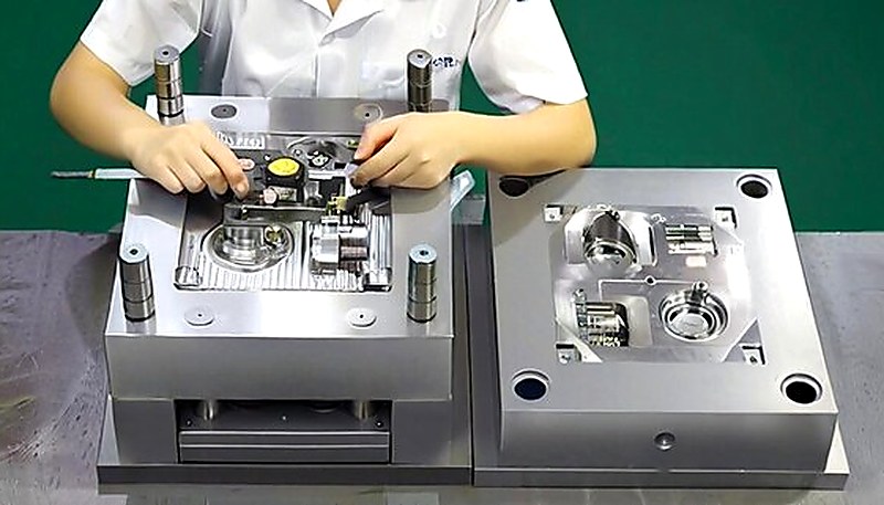
What Role Does Mold Assembly Precision Play in Final Part Accuracy?
Mold assembly precision is the alignment control that keeps cavity and core geometry repeatable at clamp-up. Even accurately machined inserts can create flash, wall-thickness error, or feature offset if leader pins, bushings, parting surfaces, sliders, or insert pockets are not fitted and verified correctly.
The critical assembly factors for precision molds are: leader pin and bushing fit (we use H7/h6 fits, providing 0.010–0.020 mm clearance per side), parting line flatness (lapped to within 0.005 mm across the mold face), insert seating (precision-ground insert pockets to ensure 100% bearing contact without rocking), and lifter/slider fits (0.02–0.05 mm clearance to allow movement while preventing flash).
We also pay close attention to the ejector plate return system. If ejector pins are not retracted to exactly the same position at cycle start, dimensional variation in part features located over those pins occurs. We use four-pillar guided ejector plates with return springs and check that all pins sit flush to cavity face (±0.02 mm) before approving a mold for production.
““Parting line flatness lapped to within 0.005 mm reduces flash and ensures consistent wall thickness at the parting plane.””真
A flat, clean parting line ensures full contact across the mold face when clamped, preventing flash formation at injection pressures up to 1,400 bar. Uneven parting surfaces—even differences of 0.02 mm—create localized gaps where thin flash forms, and the mold cannot be balanced to eliminate it without addressing the root flatness problem.
““Once a mold is precisely machined, the assembly step is straightforward and doesn’t require special attention.””偽
Mold assembly is a precision process in itself. Misaligned inserts, improperly seated leader pins, or a dirty parting surface with trapped debris can introduce positional errors of 0.05–0.2 mm—completely negating the ±0.005 mm machining precision achieved in the shop. Proper assembly requires the same discipline and measurement verification as machining.
How Does Process Control Contribute to Dimensional Consistency?
Process control is the repeatability system that keeps molded dimensions stable from shot to shot. It locks melt temperature, injection velocity, hold pressure, cooling time, ejection timing, and inspection frequency into a controlled window so part dimensions do not depend on operator adjustment or one good sample. These settings are part of the 射出成形の生産時間 cycle, where consistent timing directly translates to consistent dimensions.
Modern all-electric injection machines provide the best repeatability—injection velocity profiles repeat within ±0.1 mm/s, and injection pressure closes within ±1 bar. Hydraulic machines are acceptable for non-precision parts but show ±3–5 bar pressure repeatability that accumulates into dimensional variation on tight-tolerance work.
We implement Statistical Process Control (SPC) on all precision mold dimensions, measuring 5–10 parts per shift and plotting Xbar-R charts for critical dimensions. Our acceptance criterion is Cpk ≥ 1.67 for critical features (equivalent to ±5 sigma) before a new mold is released to full production. This typically requires adjusting process parameters to center the distribution within tolerance, not just confirming that parts are in tolerance at a single operating point.
よくある質問
射出成形の精度を向上させるための最初のステップは何ですか?
The first step is to separate mold accuracy problems from process stability problems. Measure the cavity, core, shutoff, slider, and insert positions against the approved CAD model and inspection plan before changing molding parameters. If the steel is wrong, pressure or temperature changes only hide the issue for a short time. We normally confirm critical mold dimensions first, then validate shrinkage assumptions, cooling balance, CMM inspection needs, and SPC data before approving a correction path. This avoids trial-and-error changes that make the next production run harder to diagnose.
成形部品の寸法変動をどのように低減しますか?
Dimensional variation is reduced by controlling the full chain: material drying, melt temperature, injection velocity, holding pressure, cooling time, mold temperature, and ejection timing. The mold also needs balanced cooling, stable alignment, and repeatable venting. In practice, we use process windows and Cpk targets instead of a single good sample. When the process stays centered and variation is narrow, the same mold can hold tolerance over long production runs, instead of passing only the first trial batch. That is the difference between sample approval and production capability.
なぜ精密金型で収縮補正が失敗するのですか?
Shrinkage compensation fails when the design uses generic material datasheet values without considering wall thickness, gate location, glass fiber orientation, packing pressure, and cooling rate. Two areas on the same part can shrink differently, especially on semi-crystalline materials. A safer method is to simulate location-specific shrinkage, cut steel with correction allowance, measure first samples, and then apply a controlled dimensional correction instead of guessing a single global shrinkage factor for the whole mold. This keeps correction work measurable and prevents over-cutting steel.
生産開始後、精密金型はどのくらいの頻度で検査すべきですか?
Inspection frequency depends on steel grade, resin abrasiveness, tolerance risk, and production volume. For critical features, a practical baseline is dimensional inspection at launch, after first stable production, and then every defined shot-count interval. P20 molds may need tighter checks than H13 or hardened stainless inserts. SPC signals are also important: if parts drift while still inside tolerance, inspect the mold before the next batch creates out-of-spec parts or causes a customer complaint. This turns inspection into prevention rather than late sorting.
既存の金型は新しい工具を作らずに改善できますか?
Yes, many existing molds can be improved if the root cause is measurable and enough steel-safe correction remains. Common improvements include re-machining cavity details, improving shutoff contact, polishing or reworking vents, balancing cooling, correcting insert seating, and tightening slider or lifter fits. If the issue comes from wrong part design, poor gate location, or excessive wear, a partial rebuild or new insert may be more reliable than repeated process adjustments that only move the problem. The decision should come from measured deviation, not guesswork.
How Can You Ensure Consistent Precision in Your Injection Molds?
Improving injection mold precision is not a single intervention—it’s a systematic process that spans design, tooling, and production. Each element reinforces the others: excellent shrinkage compensation is wasted without precise machining; precise machining is undermined by unbalanced cooling; balanced cooling doesn’t help if the process drifts. Only when all elements work together does true precision injection molding become consistently achievable.
In our factory, we’ve found that the highest-impact investments for precision are: validated shrinkage modeling (saves multiple dimensional correction cycles), in-process measurement during machining (directly reduces post-cut rework), and rigorous SPC in production (catches dimensional drift before parts go out of tolerance). These three practices deliver the biggest return on investment for any manufacturer pursuing tighter molded part tolerances.
If your parts are currently failing to meet tolerances, the diagnostic approach is systematic: first verify mold dimensions against original design, then verify shrinkage compensation accuracy, then analyze process SPC data. In our experience, this three-step diagnostic finds the root cause within 90% of precision failures. If you are evaluating suppliers for precision mold work, our injection molding supplier sourcing guide covers RFQ preparation, factory qualification, and commercial risk assessment.
Need a Quote for Your Injection Molding Project?
Get competitive pricing, DFM feedback, and production timeline from ZetarMold’s engineering team.
Request a Free Quote → See our Injection Molding Complete Guide for a comprehensive overview.
-
shrinkage compensation: shrinkage-compensation refers to shrinkage compensation means oversizing mold steel to account for material contraction during cooling so the finished part reaches the target dimension. ↩
-
Cpk: Cpk is a process capability index showing whether production variation is both narrow enough and centered inside the tolerance window. ↩
-
CMM: CMM refers to inspection measures three-dimensional part or mold geometry against CAD nominal data and is commonly used for first article inspection. ↩


