 コンテンツへスキップ

アン 射出成形金型1 単一の金属塊ではなく、特定の役割を持つ複数の相互接続されたシステムからなる精密な組立体です。いずれか一つでも誤ると、フラッシュ、シンクマーク、ショートショット、あるいはさらに悪い場合、修理に5桁の費用がかかる金型ができあがります。上海の工場では20年以上にわたり数千の金型を製造してきましたが、得られる教訓は常に同じです:金型の主要部品すべてを理解することが、スムーズな生産と高コストな悪夢との分かれ目となります。
- An injection mold has 6 core functional systems: gating, molding, temperature control, structural, ejection, and exhaust.
- The gating system controls how molten plastic enters the cavity — gate size and location directly affect part quality.
- Molding parts (core and cavity) define the shape, surface finish, and dimensional accuracy of the final product.
- Temperature control via cooling channels determines cycle time and prevents warpage.
- Proper ejection system design avoids part deformation and ensures consistent demolding.
This guide breaks down each main part of the injection mold, explains how they work together, and shares practical tips from real production experience. Whether you are specifying a new mold or troubleshooting an existing one, knowing these systems inside out will save you time and money.
What Is an Injection Mold and Why Does Its Structure Matter?
An injection mold and why does its structure matter is defined by the function, constraints, and tradeoffs explained in this section. If you are comparing vendors or planning procurement, our injection molding supplier sourcing guide covers RFQ prep, qualification, and commercial risk checks.
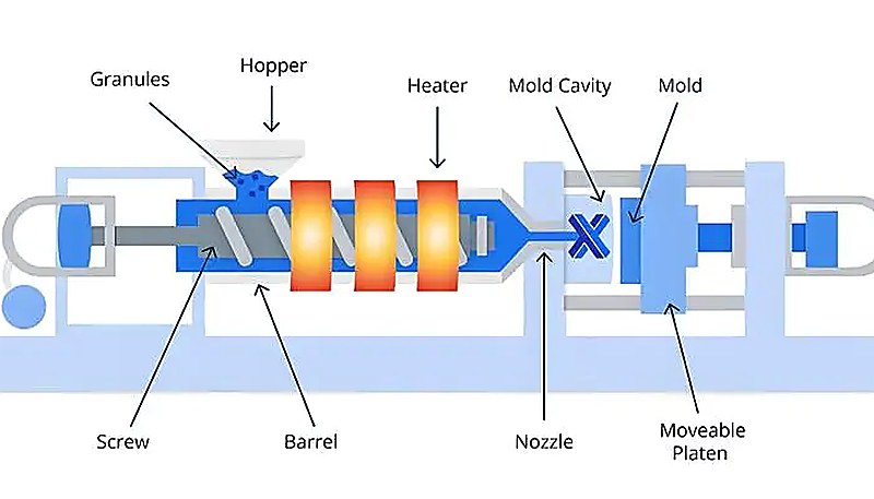
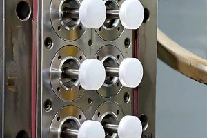
An injection mold is a custom-manufactured tool that shapes molten plastic into a specific geometry under high pressure and temperature. It consists of two primary halves — the fixed half (A-side or cavity side) mounted on the stationary platen, and the moving half (B-side or core side) mounted on the moving platen of the 射出成形 machine. When these two halves close, they form a sealed cavity where the plastic part takes shape.
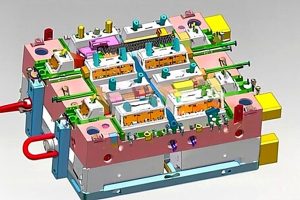
The structure of an injection mold is far more complex than it appears. A typical production mold contains 100–300 individual components, organized into functional systems. Each system must work in perfect coordination: the gating system2 delivers material, the molding parts define geometry, the cooling system solidifies the part, the ejection system removes it, the guide system ensures alignment, and the exhaust system vents trapped air and gases.
In our Shanghai factory, we run 47 injection molding machines from 90T to 1850T and maintain an in-house mold manufacturing facility. With 20+ years of experience, we have learned that mold structure decisions made during the design phase determine 70–80% of final part quality.
Why does mold structure matter so much? Because every design choice cascades through production. Gate location affects weld line position. Cooling channel layout determines cycle time and warpage. Ejection pin placement influences cosmetic quality. A well-structured mold runs reliably for hundreds of thousands of cycles; a poorly structured one becomes a constant source of defects and downtime.

What Are the Functional Systems of an Injection Mold?
The functional systems of an injection mold are the main categories or options explained in this section. Before diving into each part, it helps to see the big picture. An injection mold is organized into six functional systems, each responsible for a critical phase of the molding cycle. The table below summarizes these systems and their primary components.
| System | Primary Function | Key Components |
|---|---|---|
| ゲートシステム | Channels molten plastic from nozzle to cavity | Sprue, runners, gates, cold slug well |
| 成形部品 | Defines the shape and surface of the part | Core, cavity, inserts, sliders |
| 温度管理 | Regulates mold temperature for cooling/heating | Cooling channels, water lines, heating rods |
| 構造部品 | Supports and aligns all mold components | Mold base, guide pins, guide bushings, plates |
| 排出システム | Removes the finished part from the mold | Ejector pins, ejector plates, return pins, springs |
| 排気システム | Vents trapped air and gases from the cavity | Vent grooves, parting surface vents, ejector pin clearance |
Among these, the gating system and molding parts are in direct contact with the molten plastic. They are the most complex and variable components, requiring the highest machining precision and surface finish. The gating system² directly affects filling pattern, pressure distribution, and weld line formation. The molding parts determine dimensional accuracy, surface quality, and part strength.
How Does the Gating System Work in an Injection Mold?
ゲートシステムは、溶融プラスチックが スクリュー射出成形機 金型キャビティ内に流れ込みます。それは、スプルー(主ランナー)、枝ランナー、ゲート、コールドスラグウェルの4つの主要要素で構成されています。各要素は材料の流れ、圧力、部品品質の制御において明確な役割を果たします。当工場での試作では、この経路を 射出成形のステップ 充填、保圧、冷却、取り出しのバランスを保つようにします。
について sprue is the vertical channel that connects the machine nozzle to the runner system. Its inlet diameter is typically 0.8 mm larger than the nozzle tip diameter to prevent flash and ensure proper alignment. A standard sprue inlet ranges from 4–8 mm depending on part size, with a 3°–5° 抜き勾配3 for easy removal of the solidified sprue.
について branch runners distribute material from the sprue to individual cavities in multi-cavity molds. For balanced filling, runners should be arranged symmetrically and equidistantly. Cross-sectional shape matters: round runners offer the lowest flow resistance, but trapezoidal runners are more common because they are machined into only one mold half, reducing manufacturing cost. Runner width for most thermoplastics stays between 2–8 mm.
について ゲート is the narrowest point in the runner system and the entry point into the cavity. Gate design is one of the most critical decisions in mold engineering. A small gate increases shear heating (which lowers melt viscosity and improves flow), controls flow rate, and makes it easier to separate the part from the runner. However, if the gate is too small, it causes excessive shear stress and visible gate marks. Common gate types include edge gates, submarine gates, pin gates, and fan gates — each suited to different part geometries and materials.
について cold slug well sits opposite the sprue and catches the cold plastic that forms at the nozzle tip between shots. If this cold material enters the cavity, it causes surface defects and weak weld lines. A typical cold slug well has a diameter of 8–10 mm and a depth of 6 mm, often with a zigzag or undercut puller to help extract the sprue during mold opening.
「ゲートサイズを小さくするとせん断加熱が増加し、キャビティへの溶融樹脂の流れを改善できます。」真
True. As melt passes through a narrow gate, the high shear rate generates frictional heat, raising the local melt temperature and reducing viscosity. This improves cavity filling, especially for viscous materials. However, gates that are too small can cause excessive shear degradation of the polymer.
「丸形ランナー断面は常に最良の選択です。なぜなら、流動抵抗が最も低いからです。」偽
False. While round runners do offer the lowest flow resistance for a given cross-sectional area, they must be machined into both mold halves and require precise alignment. In practice, trapezoidal or modified U-shaped runners are often preferred because they are cut into only one half, reducing manufacturing cost and alignment complexity.
What Role Do Molding Parts Play in Shaping the Product?
Molding parts — also called cavities and cores — are the heart of any injection mold. The プラスチック部品が冷却して固化した後、型から取り出す必要があります — これは射出システムの仕事です。射出ピン⁴は最も一般的な射出要素ですが、システムには射出プレート、リターンピン、スプリング、ストリッパプレートも含まれ、場合によってはエアブラストバルブやロボットによる取り出しも使用されます。 (also called the die or female mold) forms the external shape of the product. The core (also called the male mold or punch) forms the internal features such as holes, ribs, and pockets. When the mold closes, the gap between the core and cavity is exactly the shape of the finished part.
Designing molding parts involves multiple decisions: parting line³ location, surface finish requirements, draft angles⁵ for ejection, and material selection. The parting line must be positioned to minimize undercut features and allow clean ejection. Surface finish on molding surfaces typically requires an Ra value below 0.32 μm for polished cosmetic parts — any rougher, and the surface texture transfers directly to the molded product.
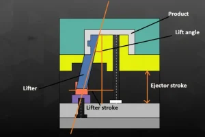
For complex geometries, molding parts often include inserts (removable blocks for hard-to-machine features), スライダー (moving cores for undercuts and side features), and angled lifters (for internal undercuts). These components add cost and complexity but are essential for producing parts with threads, snap fits, or lateral holes that cannot be molded in the normal draw direction.
8名のシニアエンジニアと月産100セット以上の金型製造能力を備えた当チームは、400種類以上のプラスチック材料にわたる成形部品設計において豊富な経験を有しています。各材料の収縮率、流動特性、冷却挙動は、コアとキャビティの設計方法に影響を与えます。
Material selection for molding parts is equally critical. Most production molds use hardened tool steel (P20, H13, S136, or 718H) with appropriate heat treatment to achieve 48–54 HRC hardness. For high-volume or abrasive materials, mold surfaces may receive additional coatings such as TiN (titanium nitride) or chrome plating to enhance wear resistance and corrosion protection.
Why Is the Temperature Control System Critical?
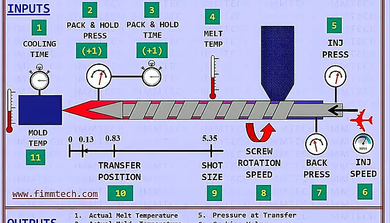
温度制御システムは、コスト、品質、生産量、用途のトレードオフを支えるため、極めて重要です。温度制御システム — しばしば単に 冷却システム と呼ばれます — は、各サイクル中の金型の作動温度を調整します。ほとんどの熱可塑性プラスチック射出成形金型では、主な機能は冷却です:溶融プラスチックから熱を除去し、変形なく取り出せる安定した部品に固化させます。
Cooling is typically the longest phase of the injection molding cycle, accounting for 50–70% of total cycle time. Even small improvements in cooling efficiency translate directly into higher production output and lower per-part cost. The most common approach uses a network of 冷却チャンネル (water lines) drilled through the mold plates, with circulating water at a controlled temperature.
Key cooling channel configurations include straight drilled channels (the simplest and cheapest), baffles (deflectors that redirect flow into blind holes), bubblers (tubes that create annular flow around core pins), and conformal cooling channels (3D-printed channels that follow the cavity contour for uniform cooling). Conformal cooling can reduce cycle time by 20–40% compared to conventional drilled channels, though it adds significant mold cost.
In some cases, the mold actually needs heating rather than cooling. Materials like polycarbonate, PEEK, and certain engineering plastics require elevated mold temperatures (80–180°C) to prevent premature freezing, reduce residual stress, and achieve proper crystallinity. Hot runner systems and cartridge heaters are used in these applications.
「ほとんどの用途において、冷却は射出成形サイクル全体の50~70%を占めます。」真
True. After the cavity is filled and packed, the part must cool enough to be ejected without warping or deforming. This solidification phase is typically the longest part of the cycle. Optimizing cooling channel design — placement, flow rate, and temperature — is one of the most effective ways to increase production throughput.
「すべての射出成形金型には冷却チャンネルのみが必要であり、加熱は決して必要ありません。」偽
False. Many engineering thermoplastics such as polycarbonate, PEEK, and nylon require elevated mold temperatures to achieve proper crystallinity and reduce residual stress. In these cases, the temperature control system includes heating elements such as cartridge heaters or hot oil circulation alongside or instead of cooling water.
How Do Structural Parts Support the Mold?
このセクションでは、金型を支える構造部品と、コスト、品質、タイミング、または調達リスクへの影響について説明します。構造部品は金型の背骨を形成します。これらはすべてを一体に保持し、金型両ハーフ間の精密な位置合わせを確保し、射出時に発生する巨大な締め付け力(通常、機械サイズに応じて50~200トン以上)に耐えます。主要な構造コンポーネントには以下が含まれます: mold base (standard frame), guide pins and bushings, support pillars, and various plates.
について mold base (also called the mold frame or bolster) is the outer structure that houses all other components. Most injection molds use standardized mold bases (such as DME, HASCO, or LKM) to reduce design and manufacturing time. The mold base includes the top clamping plate, A-plate (cavity side), B-plate (core side), support plate, ejector housing, and bottom clamping plate.
Guide pins and guide bushings ensure that the moving and fixed mold halves align precisely during closing. A standard mold uses four sets of guide pins and bushings positioned at the corners. For higher precision, additional taper interlocks or zero-degree side locks are added to the parting surface. Without proper guide alignment, the core and cavity can shift, causing flash, dimensional errors, and accelerated wear.
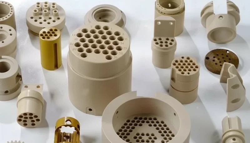
Other critical structural elements include return pins (which push the ejector plate back when the mold closes), support pillars (which prevent the B-plate from deflecting under injection pressure), and stop blocks (which set the correct mold height). Each of these components must be correctly sized and positioned to maintain mold integrity over millions of cycles.
What Makes the Ejection System Effective?
After the plastic part has cooled and solidified, it must be removed from the mold — this is the job of the ejection system. The ejector pin⁴ is the most common ejection element, but the system also includes ejector plates, return pins, springs, stripper plates, and in some cases air blast valves or robotic extraction.
ドラフト角とは、射出成形時に成形品を容易に取り外せるように、金型キャビティの垂直面に施されるわずかなテーパーのことを指します。
For thin-walled or fragile parts, stripper plates are preferred over individual pins because they distribute ejection force evenly across the entire part perimeter. For parts with deep cores or significant undercut, sleeve ejectors または angled lifters may be necessary. In all cases, the ejection system must work smoothly at production speed — any sticking or inconsistent ejection causes downtime and scrap.
Our 90T to 1850T machine range means we produce everything from tiny precision medical components to large structural parts. Each part category demands a different ejection strategy. Working under ISO 9001 and ISO 13485 systems ensures our ejection designs are validated before production begins.
How Do Guide and Exhaust Systems Ensure Quality?
Two systems that are easy to overlook but critical for quality: the ガイドシステム そして exhaust system. The guide system ensures that the moving and fixed mold halves align precisely every cycle. The exhaust system vents the air and gases that are trapped in the cavity during filling — without it, you get burns, short shots, and weak weld lines.
The guide system uses guide pins (leader pins) and guide bushings mounted on the four corners of the mold. These engage first as the mold closes, bringing the two halves into rough alignment before the core and cavity make contact. For higher precision molds, additional locating elements such as taper interlocks, straight side locks, or conical locating blocks are added at the parting surface to maintain alignment within plus or minus 0.01 mm.
The exhaust system works through shallow grooves (0.03–0.20 mm deep, 1.5–6 mm wide) machined into the parting surface, typically at the end of the melt flow path. These grooves allow trapped air and decomposition gases to escape. If exhaust is insufficient, the compressed gas heats up rapidly (adiabatic compression) and can reach temperatures that burn or discolor the plastic surface — a defect known as diesel effect or gas burn.
In addition to dedicated vent grooves, mold designers use secondary exhaust paths: the clearance between ejector pins and their holes, between sliders and their guides, and between lifters and the core. These incidental vents supplement the primary vent grooves, especially for complex parts with multiple flow fronts and weld lines.
よくある質問
What are the six main functional systems of an injection mold?
The six main systems are the gating system (delivers molten plastic), molding parts (define part geometry), temperature control system (regulates cooling and heating), structural parts (support and align the mold), ejection system (removes the finished part), and exhaust system (vents trapped air and gases). Each system must work in coordination for reliable, high-quality production. A failure in any one system — such as a blocked vent, an undersized gate, or a misaligned guide pin — can cascade into defects, downtime, and costly rework. Understanding how these systems interact is essential for specifying, reviewing, or troubleshooting injection molds.
How does the gating system affect injection molded part quality?
The gating system controls how molten plastic enters the cavity. Gate size, type, and location directly influence filling pattern, pressure distribution, weld line position, and surface appearance. An improperly designed gate can cause jetting, sink marks, flow lines, or incomplete filling. For example, a gate that is too small increases shear stress and can degrade the polymer, while a gate in the wrong location can trap air and cause gas burns. This makes gate design one of the most critical decisions in mold engineering, often validated through mold flow simulation before steel is cut.
What is the difference between a core and a cavity in a mold?
The cavity (female mold or die) forms the external shape and cosmetic surfaces of the part. The core (male mold or punch) forms the internal features such as holes, ribs, and pockets. Together, the core and cavity define the complete 3D geometry of the molded part when the mold is closed. The cavity is typically mounted on the fixed side of the mold, while the core is on the moving side where ejection occurs. Both must be machined to extremely tight tolerances — often within ±0.01 mm — to ensure part accuracy and prevent flash at the parting line.
Why is cooling channel design so important in injection molds?
Cooling typically accounts for 50–70% of the total cycle time, making it the single largest factor in production efficiency. Efficient cooling channel layout reduces cycle time, improves throughput, and prevents defects like warpage and uneven shrinkage. Advanced approaches like conformal cooling — where channels follow the cavity contour — can reduce cycle time by 20–40% compared to conventional straight-drilled channels. Poor cooling design not only slows production but also creates inconsistent part dimensions and surface quality, which is why thermal simulation is standard practice in professional mold design.
What happens if the exhaust system in a mold is insufficient?
Insufficient exhaust causes trapped air and gases to compress adiabatically, generating extreme local temperatures that can burn or discolor the plastic surface — a defect known as the diesel effect or gas burn. It also leads to short shots (incomplete filling), weak weld lines where multiple flow fronts meet, and internal voids. Proper vent grooves (0.03–0.20 mm deep) machined at the end of flow paths, combined with ejector pin clearances that act as secondary vents, prevent these issues. In multi-cavity molds, balanced exhaust across all cavities is critical for consistent part quality.
What materials are injection mold cores and cavities made from?
Most production molds use hardened tool steels such as P20, H13, S136, or 718H, heat-treated to 48–54 HRC for durability and wear resistance. P20 is the most common choice for general-purpose molds, while H13 and S136 are preferred for high-temperature or corrosive materials. For high-volume or abrasive applications, mold surfaces may receive additional coatings such as TiN (titanium nitride) or chrome plating. Prototype and short-run molds sometimes use aluminum (Al 7075) for faster machining and lower cost, though aluminum molds have significantly shorter tool life.
How many ejector pins does a typical injection mold need?
The number of ejector pins depends on part geometry, size, wall thickness, and material shrinkage behavior. A simple, small part may need only 4–8 pins, while a complex part with thin walls, deep draws, or delicate features can require 20–50 or more. The key principle is to distribute ejection force evenly across the part to prevent deformation, cracking, or sticking during demolding. For fragile parts, stripper plates or sleeve ejectors may be used instead of individual pins to provide uniform ejection force along the entire part perimeter.
Can injection molds have both heating and cooling systems?
Yes, many injection molds incorporate both heating and cooling capabilities. Engineering thermoplastics like polycarbonate, PEEK, and nylon require elevated mold temperatures (80–180°C) during filling to prevent premature freezing and achieve proper crystallinity. These molds use cartridge heaters or hot oil circulation alongside cooling water channels. During the filling and packing phases, heating maintains the mold temperature; during the cooling phase, the system may switch to active cooling to accelerate solidification. This dual-mode temperature control is standard practice in precision molding of high-performance engineering plastics.
初回から正確に設計・製造された精密射出成形金型が必要ですか?上海のエンジニアリングチームは、400種類以上の材料にわたる最適化されたゲート、冷却、取り出しシステムを備えた金型設計において20年以上の経験を有しています。次の金型プロジェクトについて相談するため、今すぐお問い合わせください — 24時間以内に詳細な技術見積もりでご返信いたします。より広範な工具製造の概要については、当社の complete guide to injection mold.
-
injection mold: injection mold refers to a precision tool used in manufacturing to shape molten plastic into a desired form by injecting material under high pressure into a cavity. ↩
-
gating system: gating system refers to the network of channels in a mold that guides molten plastic from the machine nozzle into the cavity, including the sprue, runners, and gates. ↩
-
draft angle: draft angle refers to a slight taper applied to the vertical surfaces of a mold cavity to facilitate easy removal of the molded part during ejection. ↩


 EN
EN  ES
ES  FR
FR  DE
DE  PT
PT  AR
AR  RU
RU  JA
JA  KO
KO  IT
IT  NL
NL  TR
TR  PL
PL 