 Vai al contenuto

– DFM is a proactive engineering process used to optimize part geometry for the injection molding process before tooling begins.
– Uniform wall thickness is the single most critical factor in preventing warpage, sink marks, and internal voids.
– Draft angles are mandatory for part ejection; neglecting them leads to drag marks and stuck parts.
– Ribs and bosses must follow specific thickness ratios (typically 40-60% of the nominal wall) to avoid aesthetic defects on the cosmetic side.
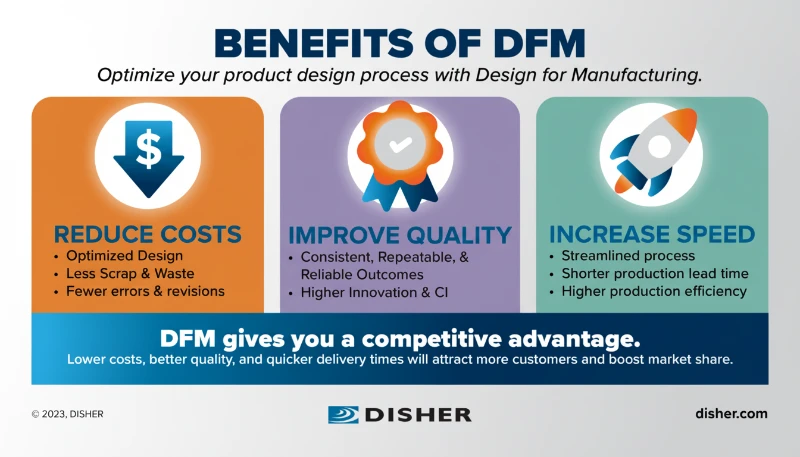
What Is Design for Manufacturing (DFM) in Injection Molding?
Progettazione per la produzione (DFM) is the engineering practice of designing products in such a way that they are easy to manufacture. In the context of stampaggio a iniezione, it involves optimizing the 3D CAD data of a plastic part to align with the physics of molten plastic flow, cooling rates, and mechanical ejection.
A robust DFM review occurs before the steel is cut for the mold. It identifies potential issues such as undercuts, insufficient draft, or thick sections that could cause defects. Implementing DFM injection molding guidelines1 early in the development cycle can reduce tooling costs by 20-30% and shorten lead times significantly.

What Are the 10 Essential DFM Rules?
1. Maintain Uniform Wall Thickness
The cardinal rule of plastic design is uniformity. Molten plastic shrinks as it cools. If a part has varying thicknesses, thick sections cool slower than thin sections, causing differential shrinkage. This leads to warpage and sink marks (depressions on the surface).
- Guideline: Maintain a constant wall thickness throughout the part.
- Transition: If thickness changes are necessary, use a gradual ramp (3:1 ratio) rather than a sharp step.
2. Apply Proper Draft Angles
Draft is the taper applied to the faces of the part perpendicular to the parting line. Without draft, friction between the part and the mold steel during ejection will cause drag marks or cause the part to stick in the mold.
- Guideline: Apply at least 1° to 2° of draft to all vertical walls.
- Texture: For textured surfaces, add an additional 1.5° per 0.001 inch (0.025 mm) of texture depth to ensure correct draft angles design2.
Adding draft angles significantly changes the part's function and aesthetics, so they should be avoided on cosmetic surfaces.Falso
Draft angles are essential for manufacturability. While they slightly alter geometry, omitting them results in cosmetic drag marks and ejection failures. They should be integrated into the aesthetic design.
Draft angles must be applied to both the cavity (A-side) and the core (B-side) of the mold.Vero
Draft is required on all vertical surfaces relative to the direction of pull to facilitate release from both sides of the tool.
3. Round Corners (Radii)
Sharp corners are stress concentrators. In injection molding, plastic flows more smoothly around rounded corners. Sharp corners inhibit flow and can lead to part failure under load.
- Guideline:
- Internal Radius: $\ge 0.5 \times \text{Wall Thickness}$
- External Radius: $\text{Internal Radius} + \text{Wall Thickness}$
4. Optimize Rib Design
Costole are used to increase stiffness without adding thickness. However, if a rib is too thick where it joins the main wall, it creates a thick mass of material that cools slowly, causing a sink mark on the opposite side (the cosmetic face).
- Guideline: Rib design plastic parts3 dictates that rib thickness at the base should be 40% to 60% of the nominal wall thickness.
5. Manage Boss Design
I capi are cylindrical features used for screw reception or location. Like ribs, they can cause sink marks if not cored out properly.
- Guideline: Standalone bosses should be connected to the wall via gussets for strength. The wall thickness of the boss itself should follow the 60% rule relative to the main wall.
6. Avoid Undercuts (Or Design for Them)
Undercuts are features that prevent the mold from opening in a straight line (e.g., a hole in the side of a part, or a snap-fit latch). These require complex mold mechanisms called "side-actions" (slides or lifters), which increase tooling costs.
- Guideline: Design features such as snap-fits to be "in the line of draw" (pass-through core) whenever possible to eliminate the need for slides.
7. Define Tolerances Realistically
Tight tolerances increase mold cost and processing difficulty. Specifying +/- 0.002 inches on every dimension is rarely necessary.
- Guideline: Adhere to standard injection molding tolerance standards4 such as DIN 16901 o ISO 20457.
- Fine Tolerance: +/- 0.05 mm (precision parts).
- Standard Tolerance: +/- 0.2 mm (general enclosures).
8. Gate Location Strategy
Il cancello is the entry point of the plastic. Its location dictates flow lines, weld lines (where two flow fronts meet), and potential air traps.
- Guideline: Gate into the thickest section of the part to allow for proper packing. Avoid gating on high-stress areas or cosmetic surfaces.
9. Material Selection and Shrinkage
Different materials shrink at different rates. The mold must be cut larger than the final part to account for this.
- Esempio: Policarbonato (PC) shrinks ~0.5-0.7%, while Polietilene (PE) can shrink ~1.5-3.0%. Changing materials after the mold is built can be disastrous if shrinkage rates differ drastically.
10. Surface Finish Specification
Surface finish affects draft requirements and tooling cost.
- Guideline: Utilizzo SPI (Society of the Plastics Industry) standards.
- SPI A-1: High Diamond Polish (High Cost, High Draft).
- SPI C-3: Stone Finish (Medium Cost).
- SPI D-2: Textured Blast (Hides sink marks/fingerprints).
Wall thickness should be maximized to ensure the strongest possible plastic part.Falso
Thicker walls lead to longer cooling times, higher material costs, and an increased risk of internal voids and sink marks. Ribs should be used for strength instead of thickening the entire wall.
Proper rib design requires the rib thickness to be roughly 50% to 60% of the adjacent wall thickness.Vero
This ratio prevents the accumulation of excessive material mass at the intersection, minimizing the risk of sink marks on the visible surface opposite the rib.
Reference Parameter Table: DFM Standards
| Caratteristica | Recommendation | Scopo |
|---|---|---|
| Spessore della parete | 1.5mm – 3.0mm (Average) | Ensure even cooling, prevent warpage. |
| Draft Angle (Standard) | 1° – 2° | Prevent sticking, ease ejection. |
| Draft Angle (Textured) | +1.5° per 0.001" depth | Prevent drag marks on texture. |
| Rib Thickness | 40% – 60% of Wall | Prevent sink marks on the cosmetic side. |
| Altezza della nervatura | < 3x Wall Thickness | Prevent filling issues and trapped gas. |
| Corner Radius | 25% – 50% of Wall | Reduce stress concentration. |
Practical DFM Tips for Engineers
- The "Thick-to-Thin" Rule: Always design flow to move from thick sections to thin sections. Flowing from thin to thick creates "hesitation" and can cause filling problems.
- Coring Out: If you have a thick block of material, remove the center ("core it out") leaving only uniform walls. This saves weight and cycle time.
- Weld Line Placement: Discuss with your molder where weld lines will occur. Move gates to push weld lines to non-critical or non-cosmetic areas.
Domande frequenti (FAQ)
Q: Can I vary wall thickness if I use a high-performance material?
A: Generally, no. Even high-performance materials like Polyamide 66 (PA66) o Polyether Ether Ketone (PEEK) are subject to physics. Differential cooling will still cause internal stresses and warpage regardless of material grade.
Q: How do I fix a sink mark without changing the mold design?
A: Process adjustments can help (increasing pack pressure, extending cooling time), but they increase part cost. The best fix is DFM: coring out the thick section causing the sink.
Q: What is the difference between a "shut-off" and a "slider"?
A: A slider is a moving mechanism to form an undercut. A shut-off creates a hole or feature by bringing two faces of the mold (core and cavity) together vertically, eliminating the need for a slider. Shut-offs are cheaper but require draft angles of 3°–5°.
Q: Why is corner radius so important?
A: Sharp corners impede plastic flow and create stress risers. A part with sharp corners is significantly more likely to crack upon impact or ejection than one with proper fillets.
Q: Do prototype molds require the same DFM as production molds?
A: Yes. If a prototype mold is designed without proper draft or wall uniformity, the prototype parts will fail or warp. You will not get valid test data, and the design will need to be changed for production anyway.
Sintesi
Mastering the 10 essential DFM rules is the most effective way to ensure a successful injection molding project. By prioritizing spessore uniforme della parete, applying correct angoli di sformo, and optimizing rib design plastic parts, engineers can eliminate common defects like sink marks and warpage. Adhering to injection molding tolerance standards and conducting a thorough DFM review before tooling production begins ensures that the final product is not only manufacturable but also cost-effective and robust.
-
Detailed guide on Design for Manufacturability principles that help reduce tooling costs and cycle times. ↩
-
Technical explanation of how draft angles facilitate part ejection and the specific requirements for textured surfaces. ↩
-
Best practices for structural reinforcement, focusing on thickness-to-wall ratios to prevent aesthetic defects. ↩
-
International standards providing the framework for establishing achievable tolerances in plastic molding. ↩


