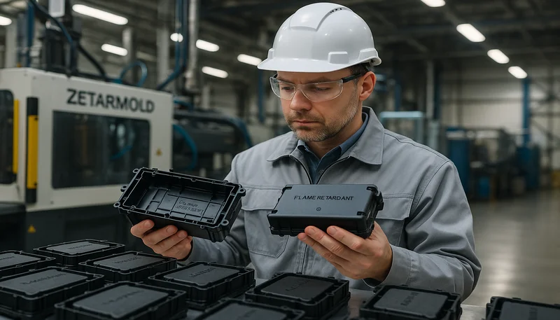
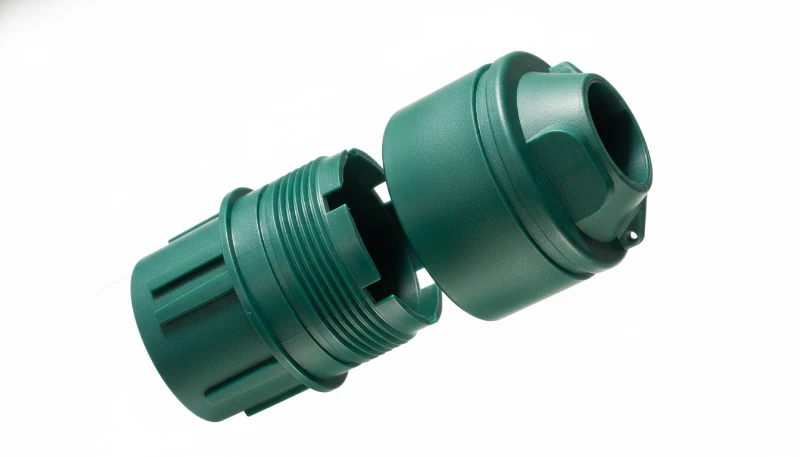
Before you commit to a full production run with an injection molding supplier, the sample approval process is your last line of defense. A properly evaluated sample catches dimensional drift, surface defects, and material issues before they multiply across 10,000 parts. Skipping or rushing this step is the single most common reason we see buyers scrambling with late deliveries, quality disputes, and costly tooling rework. This guide walks you through exactly how to evaluate supplier samples — from initial visual checks to functional testing — so you can sign off with confidence. We draw on injection molding production experience across thousands of projects to give you a practical, no-nonsense framework.
- Sample approval is your final quality gate — never skip it
- Dimensional inspection alone is not enough — combine visual, material, and functional checks
- Always define acceptance criteria before samples arrive
- Request material certificates and traceability alongside physical samples
- A documented approval process protects both buyer and supplier from disputes
What Is Sample Approval in Injection Molding?
Sample approval is the formal verification that molded parts meet your specs before you authorize mass production. It bridges the gap between prototype and full-scale manufacturing. In practice, this means the supplier produces a small batch of parts using the actual production tooling and process parameters, then submits them to you for evaluation. You compare each dimension, surface finish, and material property against the agreed-upon drawing and specification. Only when every criterion passes do you issue a formal approval — often called a First Article Inspection (FAI)1 sign-off or PPAP2 submission. Why does this matter?
In our experience working with buyers from over 30 countries, roughly 1 in 4 first samples reveals a measurable deviation that requires correction. These range from minor cosmetic blemishes to critical dimensional shifts that would cause assembly failures. Catching them at the sample stage costs a fraction of what it would take to fix 50,000 defective parts already shipped. The sample approval process also serves another purpose: it locks in the production parameters. Once the sample is approved, the supplier should run the same machine settings, material batch, and cycle conditions for the full production order. Any deviation after approval becomes a contractual quality issue.
A robust sample approval workflow typically includes dimensional inspection, visual assessment, material verification, functional testing, and documentation review.
"Sample approval should always include dimensional, visual, material, and functional checks."True
Relying on dimensional data alone misses surface defects, material substitutions, and functional failures that can cause costly product recalls.
"If a sample passes dimensional inspection, you can safely skip material verification."False
Material verification is independent of dimensional accuracy. A supplier may use cheaper resin that produces dimensionally correct parts but has inferior mechanical properties.
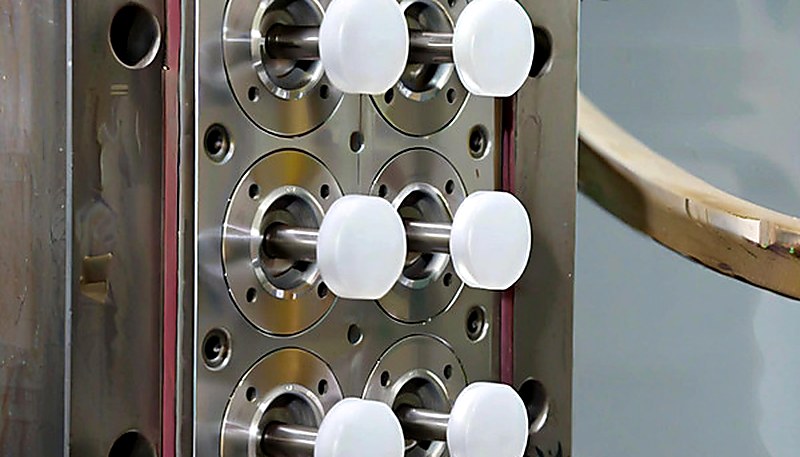
How to Set Up Your Sample Evaluation Criteria?
Setting up clear evaluation criteria is essential before samples arrive — define tolerances, surface finish, and material grades in a signed form. This is not a step you can wing.
Surface finish is typically specified using VDI 34003 standards (VDI 12 to VDI 45) or SPI standards (A-1 to D-3). A glossy cosmetic face needs an SPI A-2 or better, while a hidden structural rib might be fine at SPI C-1. Make sure your supplier knows which surfaces are cosmetic A-surfaces and which are functional B-surfaces. Material requirements should reference a specific grade from a named manufacturer — not just “ABS” or “PC.” For example, specify “SABIC Cycolac MG47” instead of generic ABS. This ensures the supplier cannot substitute a cheaper grade that may have different impact strength, melt flow index, or colorability. Document everything in a Sample Approval Form (SAF) that both parties sign before tooling begins.
The SAF should list: critical dimensions with tolerances, surface finish per surface zone, material grade and color (Pantone/RAL reference), required test reports (dimensional report, material certificate, color match report), and the number of sample pieces to be submitted.
What Does Dimensional Inspection Involve?
Dimensional inspection compares measured part dimensions against drawing tolerances using CMMs, calipers, and optical equipment. It tells you whether the molded part matches the design intent within acceptable tolerances. Here is how to do it right. First, ensure the supplier measures a statistically meaningful number of samples — we recommend at least 5 pieces from different cavities (for multi-cavity molds) and different cycles. Measuring only one piece tells you nothing about process consistency. The supplier should provide a dimensional inspection report (often called an FAI report) that lists every called-out dimension on the drawing, the nominal value, the tolerance band, and the actual measured values for each sample piece.
Look for dimensions that are trending toward the tolerance limit — even if they are technically “in spec,” a dimension consistently sitting at +0.24 mm on a ±0.25 mm tolerance is a red flag that the process is not centered. Common measurement tools include coordinate measuring machines (CMMs) for complex geometries, optical comparators for profile checks, micrometers and calipers for linear dimensions, and surface roughness testers for finish verification. At our facility, we use Zeiss CMM equipment for critical dimensions and project-specific go/no-go gauges for high-volume production checks. Pay special attention to features that are prone to shrinkage variation: wall thickness transitions, rib bases, and areas near gates.
These locations tend to show the most dimensional deviation between sample and production because they are sensitive to packing pressure and cooling uniformity.
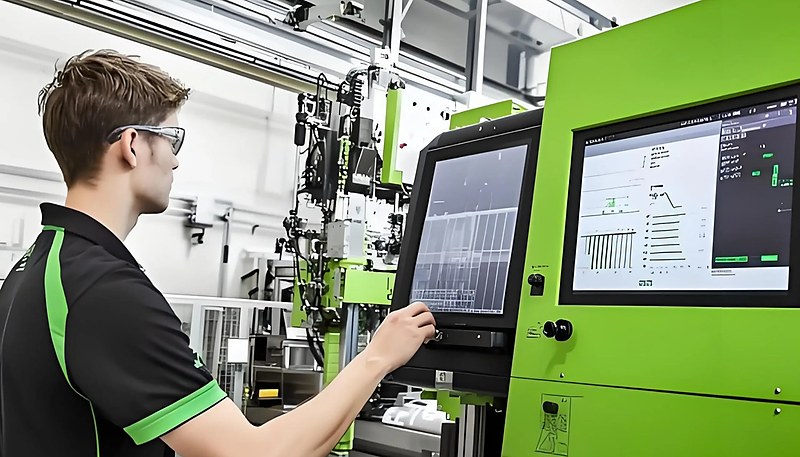
How to Perform Visual and Surface Quality Checks?
Visual inspection is the process of examining parts under controlled lighting to catch surface defects that dimensional data alone cannot reveal. A part can measure perfectly and still be unacceptable due to cosmetic flaws.
a reject. Sink marks — depressions caused by uneven shrinkage, typically over thick sections or ribs. Shallow sink marks may be acceptable on non-visible surfaces but are never acceptable on A-surfaces.
Weld lines — visible seams where two flow fronts meet. On structural parts, weld lines reduce strength at that joint. On cosmetic parts, they are often unacceptable regardless of structural impact. Flow marks and streaks — visible patterns showing the flow path of the melt. These indicate suboptimal gate location, injection speed, or mold temperature. Ejector pin marks — indentations or raised marks where ejector pins push the part out of the mold. Deep ejector marks suggest the ejection system needs adjustment or the part is sticking. Color inconsistency — streaks, patches, or gradients of varying color intensity. This usually indicates insufficient mixing of colorant or masterbatch, or contamination in the barrel.
Rate each defect type on a severity scale and compare against your SAF. For consumer-facing products, we recommend creating a visual limit sample (a “golden sample” with the maximum acceptable defect level) that both parties agree on before production.
Why Is Material Verification Critical?
Material verification is the confirmation that your supplier used the exact polymer grade you specified. Substitution is more common than most buyers realize.
RoHS and REACH compliance certificates if your product is sold in regulated markets (EU, medical devices, consumer electronics). For critical applications, consider sending a sample piece to an independent lab for material identification testing. Techniques like FTIR spectroscopy can confirm the polymer family, while DSC (Differential Scanning Calorimetry) can verify the specific grade and detect filler content. We have seen cases where a supplier quoted PC-ABS but molded with plain ABS to cut costs. The parts looked identical but had 40% lower impact strength — a defect that only shows up when the product is dropped in the field. Material verification at the sample stage prevents this class of failure.
If your part uses injection mold tooling with multiple cavities, verify that all cavities produce consistent material properties. Sometimes cavity-to-cavity variation in cooling can create subtle but measurable differences in crystallinity and mechanical performance.
"You should always request samples from a continuous production run, not hand-picked pieces."True
Hand-picked or specially produced samples may not represent normal production quality. Samples from a continuous run reveal the actual process consistency.
"Once samples are approved, the supplier can freely adjust process parameters to optimize production speed."False
Sample approval locks in process parameters. Any changes after approval constitute a process change that requires re-qualification.
What Functional Tests Should You Run on Samples?
Functional testing is the process of verifying that a sample part works as intended under real conditions.
Compare results against the material datasheet values and your design safety factors. A part that meets dimensional spec but fails a drop test is not approved. Environmental testing — if your product will be exposed to temperature extremes, humidity, UV, or chemicals, subject the samples to accelerated aging tests. A common mistake is approving samples tested at room temperature when the final product will see 80°C operating conditions. Electrical testing — for electronic housings or connectors, verify insulation resistance, dielectric strength, and EMI shielding performance. Material substitution (see previous section) often shows up first in electrical property deviations.
Life cycle testing — for parts with moving features (hinges, clips, latches), cycle the mechanism to verify it meets the specified life requirement. A living hinge designed for 10,000 cycles that fails at 2,000 is a critical defect. Document all functional test results alongside dimensional and visual data in your sample approval record. This creates a complete baseline that you can reference if quality drifts during production.
Each of these pre-production samples undergoes rigorous dimensional and functional evaluation before approval is granted for full-scale manufacturing.
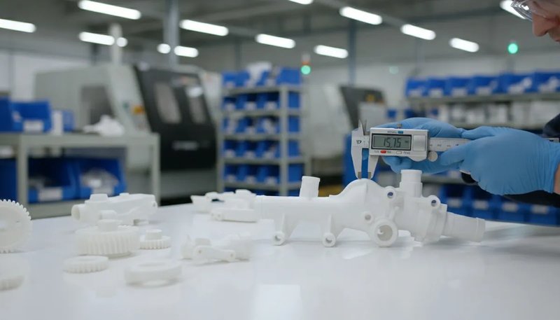
Every dimension, surface defect observation, and test result should be recorded with timestamps, inspector names, and measurement equipment identifiers. This level of detail creates an auditable trail that supports both internal quality reviews and external customer requirements.
How to Document and Formalize Sample Approval?
Documentation is what turns a subjective approval into a defensible, repeatable quality process. Without proper documentation, you have no evidence if things go wrong during production.
Material certificates — CoA from the resin manufacturer, batch traceability records, and any applicable regulatory compliance documents. Visual inspection record — photographs of each sample from multiple angles, with defect annotations. Include the agreed-upon limit sample photo for comparison. Functional test results — raw test data, pass/fail summary, and any deviations from the test protocol.
Sample Approval Form (SAF) — the master document that lists all acceptance criteria and has signature fields for both the buyer’s and supplier’s quality representatives. The SAF should explicitly state: “Approved for production,” “Approved with conditions,” or “Rejected — resubmission required.” We recommend using the PPAP (Production Part Approval Process) framework if your industry supports it. PPAP Level 3 is a good default — it includes dimensional results, material test results, process flow diagram, and initial process studies. Keep all sample approval records for at least the production life of the part plus one year. In regulated industries (medical, automotive), retention requirements may be longer. These records are your insurance policy if a quality dispute arises months or years later.
What Are Common Red Flags During Sample Evaluation?
Red flags are warning signs that suggest the sample may not represent real production quality. After reviewing thousands of submissions, certain patterns emerge that should make any experienced buyer pause.
Excessive cycle time during sampling — if the supplier mentions that the sampling cycle time was significantly longer than the quoted production cycle, the parts may be better than what you will get in production. Longer cycles mean more cooling time, which reduces warpage and shrinkage — benefits that disappear when they speed up for production. Reluctance to share process parameters — a transparent supplier will share injection pressure, speed profiles, holding pressure, and mold temperature settings. If they treat these as trade secrets, they may be hiding an unstable process. Pushback on third-party verification — if you request an independent lab test and the supplier resists, that resistance itself is information.
Reliable suppliers welcome third-party verification because it builds trust. Inconsistency between cavities — in multi-cavity molds, if parts from different cavities show significant variation in dimensions or appearance, the mold may need balancing before production begins.
How to Handle Sample Rejection and Resubmission?
Sample rejection is a normal part of the process, not a failure — how you handle it determines whether the next round passes. Be specific about what failed and why.
parameter they changed, why the deviation occurred, and what they will do differently. This prevents the trial-and-error approach that wastes everyone’s time. Third, set a clear resubmission timeline. A common mistake is leaving the timeline open-ended.
Agree on a specific date for the next sample submission — typically 5-10 business days after rejection for minor issues, or 15-20 business days if tooling modifications are needed. For tooling modifications, be aware that changes to the steel (adjusting cavity dimensions, adding or moving gates, modifying cooling channels) are permanent. Always ask the supplier to simulate the proposed change using mold flow analysis before cutting steel. This reduces the risk of overcorrection. In our factory, we typically budget for 2-3 sample rounds before final approval. If a project reaches round 4 without passing, it usually indicates a fundamental issue with the part design or mold concept that requires a broader engineering review rather than incremental parameter adjustments.
Finally, once the corrected samples pass all criteria, do a confirmation run of 50-100 pieces to verify that the corrected process is stable. This confirmation run bridges the gap between the carefully controlled sample condition and real production conditions.
In our Shanghai factory, we run 47 injection molding machines and have 10+ QC specialists dedicated to sample evaluation and first article inspection. With 20+ years of experience supplying molded parts to international buyers, we understand that a thorough sample approval process is the foundation of every successful production run.
Frequently Asked Questions
How Many Sample Pieces Should a Supplier Provide for Approval?
Most suppliers provide 3 to 10 sample pieces for initial evaluation. For single-cavity molds, request at least 5 pieces from consecutive cycles to assess process consistency and repeatability. For multi-cavity molds, request 3 to 5 pieces per cavity so you can compare cavity-to-cavity variation and verify mold balance. If your part has critical cosmetic requirements, ask for additional pieces to use as visual limit samples that define the acceptable defect threshold. The exact quantity should be defined in your Sample Approval Form before tooling begins.
What Is the Difference Between FAI and PPAP?
FAI (First Article Inspection) focuses specifically on dimensional verification of the first production parts against engineering drawings. It confirms that the tooling produces parts within specified tolerances. PPAP (Production Part Approval Process) is a much broader quality framework, originally developed by the automotive industry through AIAG, that includes dimensional results, material testing, process flow diagrams, process capability studies, and appearance approval reports. PPAP has multiple submission levels (1 through 5), with Level 3 being a common default for injection molding projects.
How Long Does the Sample Approval Process Typically Take?
The complete sample approval cycle typically takes 2 to 4 weeks from start to finish. This includes the sample molding phase (5 to 10 business days depending on complexity), international shipping (3 to 7 days via air freight), and your internal inspection and review process (3 to 5 business days). If the first sample round is rejected, add another 2 to 3 weeks for corrective action and resubmission. We recommend budgeting for 2 to 3 total sample rounds when planning your project timeline.
Can I Approve Samples Remotely Without Visiting the Factory?
Yes, remote sample approval is both common and practical when you follow a structured process. Require the supplier to send a complete digital package that includes high-resolution photographs from at least 8 angles, a dimensional inspection report with CMM data, material certificates with batch traceability, and video of any functional tests being performed. For critical applications or high-value tooling, supplement the digital review with a third-party inspection agency visit to the factory. Many experienced buyers use remote approval for initial rounds and visit for the final sign-off.
What Happens if Production Parts Differ from Approved Samples?
If production parts deviate from your approved samples, you have a documented contractual basis to reject the shipment and require corrective action. This scenario is exactly why thorough sample documentation matters. Request a formal root cause analysis from the supplier along with a corrective action plan. Common causes include material batch changes, progressive tooling wear, or process parameter drift during extended production runs. Having the documented process parameters from the approved sample run makes it easier to identify what changed and how to correct it.
Should I Use the Same Inspection Criteria for Prototypes and Production Samples?
No, prototype samples and production samples serve fundamentally different purposes and should be evaluated against different criteria. Prototype samples validate the design concept and basic form factor, often produced using 3D printing or soft tooling methods. Production samples come from the actual production tooling under normal conditions and should be evaluated against full production-level tolerances, surface finish requirements using VDI 3400 or SPI standards, and material specifications. Tightening acceptance criteria from prototype to production is both normal and expected in professional manufacturing.
Need a reliable injection molding partner with a proven sample approval process? With 20+ years of experience, 47 injection molding machines ranging from 90T to 1850T, and a dedicated team of 10+ QC specialists, ZetarMold provides thorough first article inspection and sample documentation for every project. Our English-speaking project managers guide you through each step — from initial sample submission to final approval. Get a Free Quote and let us show you how a professional sample approval process protects your production quality.
First Article Inspection (FAI): First Article Inspection is a formal quality verification method in which the first production parts from a new tooling or process are measured and tested against design specifications to confirm that the manufacturing process is capable of producing conforming parts. ↩
PPAP: Production Part Approval Process is a standardized framework developed by the automotive industry (AIAG) that defines the evidence a supplier must submit to demonstrate that their production process consistently meets customer engineering requirements. ↩
VDI 3400: VDI 3400 is a surface finish standard published by the Association of German Engineers that classifies mold surface textures used in injection molding, ranging from VDI 12 (fine) to VDI 45 (rough). ↩