 Skip to content

- Conductive injection-molded plastics achieve shielding effectiveness of 20–60 dB, sufficient for most FCC/CE Class B consumer electronics.
- Carbon-fiber-loaded and stainless-steel-fiber compounds reach surface resistivity below 10 Ohms/sq, enabling 40–60 dB attenuation.
- In-mold conductive coating (IMCC) eliminates secondary spray steps and cuts per-part cost by 15–25% in high-volume runs.
- Wall thickness, gate location, and weld-line management are the three process variables that most affect shielding consistency.
- ZetarMold has produced EMI-shielded enclosures for automotive radar, medical monitors, and industrial IoT devices across 47 active injection molding machines.
What Is EMI Shielding in Injection Molding and Why Does It Matter?
EMI shielding injection molding integrates 1 suppression directly into the plastic part during the molding process, achieving attenuation of 20–60 dB without post-process metal plating. Conventional plastic enclosures are transparent to radio-frequency (RF) fields above 30 MHz; adding 15–30% 2 by weight converts the resin into a Faraday-cage-equivalent structure. In our factory, we process over 200 EMI-grade compounds annually and routinely hit 40 dB SE for automotive and medical customers.
Regulatory drivers make shielding non-negotiable: FCC Part 15 limits radiated emissions from Class B digital devices to 100 μV/m at 3 m for frequencies above 30 MHz, while CISPR 32 imposes equivalent limits in Europe. Devices that fail pre-compliance testing face delayed market entry and costly redesigns. Injection-molded shielded housings, when designed correctly, provide consistent batch-to-batch performance because the shielding agent is locked inside the polymer matrix rather than applied as a separate coating layer.

Which Conductive Materials Deliver the Best EMI Shielding Performance?
Conductive fillers blended into the base thermoplastic resin create the shielding effect. Carbon-fiber-reinforced compounds (15–30% CF loading) achieve 3 of 2–8 Ω/sq and 4 of 35–55 dB across 100 MHz–3 GHz—making them the most cost-effective option for mid-range EMI requirements. Stainless steel fiber (SSF) composites at 5–15% loading reach even lower resistivity (1–5 Ω/sq) and exceed 50 dB SE, but they increase material cost by 3–5× compared to base resin. Carbon black-loaded grades are the entry-level choice: 20–30% loading yields 20–30 dB SE at resistivity around 100–1,000 Ω/sq, adequate for low-frequency interference suppression.
Nickel-coated carbon fiber offers a hybrid approach—carbon provides structural rigidity while the nickel coating lowers surface resistivity to below 1 Ω/sq. This material is favored for 5G mmWave enclosures requiring SE above 60 dB at frequencies up to 77 GHz. When selecting material, engineers must also consider mechanical trade-offs: high CF loadings above 30% increase brittleness (notched Izod drops from 80 to 30 J/m) and require adjusted gate sizing and higher injection pressures (1,200–1,500 bar) to prevent fiber breakage during flow.
| Material | Loading (%) | Surface Resistivity (Ω/sq) | SE Range (dB) | Relative Cost |
|---|---|---|---|---|
| Carbon black / PP | 20–30% | 100–1,000 | 20–30 | Low (1×) |
| Carbon fiber / PA6 | 15–30% | 2–8 | 35–55 | Medium (2×) |
| Stainless steel fiber / ABS | 5–15% | 1–5 | 40–60 | High (4×) |
| Nickel-coated CF / PC | 10–20% | <1 | 50–65 | Very High (6×) |
| Metallic flake / ABS | 20–40% | 5–50 | 25–45 | Medium (2.5×) |
How Does the Injection Molding Process Affect EMI Shielding Effectiveness?
Process parameters directly determine whether conductive fillers remain uniformly distributed throughout the part. Melt temperature must stay within the compound’s processing window—for carbon-fiber PA6, this is typically 250–270°C—to prevent fiber settling and maintain resistivity uniformity. Injection speed affects filler orientation: faster fill (200–300 mm/s) aligns fibers in the flow direction, which can create anisotropic shielding; slower fill (50–100 mm/s) with sequential valve gating reduces orientation bias by up to 40%.
Weld lines are the most critical EMI vulnerability in injection-molded enclosures. Where two flow fronts meet, conductive fibers align parallel to the weld and lose their cross-linking connectivity, causing local SE to drop by 10–20 dB. To mitigate this, we reposition gates to push weld lines to non-critical faces, use mold flow analysis to simulate fiber orientation before cutting steel, and specify a minimum wall thickness of 2.5 mm at weld-line zones. Proper cooling uniformity (±3°C mold surface temperature) also prevents differential shrinkage that could crack the conductive network.
What Are the Main EMI Shielding Methods for Injection-Molded Parts?
Four primary methods are used in practice: (1) Conductive-filled resin molding—the subject of most of this guide—where shielding is inherent to the molded material; (2) In-mold conductive coating (IMCC), where a conductive paint is sprayed inside the open mold cavity before injection, bonding to the part surface during fill; (3) Post-mold metal plating (electroless nickel or vacuum metallization); and (4) Conductive gaskets combined with standard plastic housings. Each method has a different cost-volume profile and SE ceiling.
How Does In-Mold Conductive Coating Compare to Post-Mold Plating?
IMCC has gained traction in automotive applications because it eliminates the VOC emissions of post-mold spray and achieves 30–45 dB SE with only 20–40 μm coating thickness. The coating layer is applied robotically in under 30 seconds, and the heat of injection (240–280°C) ensures adhesion without secondary curing. Post-mold electroless nickel plating achieves higher SE (50–70 dB) but adds 2–3 days of processing time and requires chemical waste management. For low-volume injection molding programs under 5,000 parts, conductive-filled resin is typically the most economical since tooling investment is unchanged.
Are Conductive Plastics Reliable for EMI Shielding Without Coatings?
“Conductive-filled injection-molded plastics can achieve shielding effectiveness above 40 dB without secondary processing.”True
Carbon-fiber-loaded compounds at 20–30% loading consistently achieve 40–55 dB SE across 100 MHz–3 GHz in production parts. The shielding is integral to the part, requiring no post-mold coating, plating, or insert insertion steps. Our factory production data confirms this range across more than 50 active part numbers in automotive and industrial categories.
“Adding more conductive filler always increases shielding effectiveness proportionally.”False
Above a critical threshold (typically 25–30% by weight for carbon fiber), additional filler yields diminishing SE returns while increasing material cost, brittleness, and processing difficulty. Beyond 30% CF loading, notched Izod impact strength can drop below 25 J/m, making parts prone to cracking under mechanical stress. Fiber breakage during high-shear injection also shortens fiber aspect ratio, reducing conductivity network connectivity and plateauing SE improvement.
| Method | SE Range (dB) | Relative Cost | Best Application |
|---|---|---|---|
| Conductive-filled resin | 20–60 | Low | High-volume integral shielding |
| In-mold conductive coating | 30–45 | Medium | Complex shapes, no post-process |
| Post-mold electroless nickel | 50–70 | High | Maximum SE requirement |
| Conductive gasket + standard plastic | 20–40 | Low | Retrofit or serviceable designs |
How Are Weld Lines and Gate Placement Optimized for EMI-Shielded Parts?
Mold flow analysis is indispensable for EMI enclosure design. By simulating fiber orientation maps before cutting steel, engineers can identify weld-line locations and evaluate gate relocation strategies. In a recent automotive radar housing project, moving from a single center gate to a 3-point valve-gated system shifted the weld lines from the antenna aperture face to a mounting flange, raising the measured SE at 2.4 GHz from 28 dB to 44 dB—a 57% improvement from a mold design change alone.
Gate design also affects fiber integrity. Fan gates and edge gates with minimum land length (0.5–1.0 mm) minimize fiber breakage during injection. Sub-gates and pin gates create higher shear and shorter fiber length, reducing conductivity. For wall sections below 2 mm, hot-runner systems with valve gates set to 240–260°C melt temperature maintain fiber aspect ratio better than cold-runner sprue-gated tools. Part ejection must also avoid stress cracking at weld lines: draft angles of 1.5–2° per side and polished tool surfaces (Ra ≤ 0.4 μm) reduce ejection force by 30–40%.

What Wall Thickness and Design Guidelines Apply to EMI-Shielded Enclosures?
Minimum recommended wall thickness for EMI-shielded injection-molded parts is 2.0–2.5 mm; below 2.0 mm, conductive fiber networks become discontinuous and SE drops sharply. For carbon-black-filled grades, 3.0 mm is the practical minimum. Apertures and ventilation slots must be designed per the rule that slot length should not exceed λ/20 at the highest design frequency: at 2.4 GHz (λ = 125 mm), maximum slot length is 6.25 mm. Circular holes larger than λ/10 require conductive mesh or wire-grid inserts to maintain SE.
How Do Apertures and Ribs Affect EMI Shielding in Molded Parts?
Rib design follows the same 2:1 rule as standard injection molding—rib height should not exceed twice the wall thickness—but for EMI parts, rib width should be 60–75% of wall thickness (versus 50% for standard parts) to maintain conductivity continuity through the rib section. Corner radii of ≥0.5 mm prevent stress concentration and preserve the conductive fiber network at bends. In our factory, we design and test every EMI enclosure with a design for manufacturability review that includes an SE simulation before tooling approval.
Do Aperture Dimensions Directly Determine EMI Compliance?
“Apertures and slots in EMI enclosures must be designed relative to the wavelength of the highest design frequency.”True
The fundamental principle of aperture EMI leakage is that any opening longer than λ/20 at the target frequency acts as an antenna and radiates or admits interference. At 2.4 GHz (Wi-Fi/Bluetooth), λ = 125 mm, so maximum slot length is 6.25 mm. Designers who ignore this and use standard ventilation-slot templates (often 10–15 mm) will fail radiated emissions testing at frequencies above 1 GHz.
“Post-mold conductive coatings are always superior to filled-resin shielding because they cover the entire surface uniformly.”False
While conductive coatings do provide surface uniformity, they are vulnerable to adhesion failure, mechanical abrasion, and chemical attack in harsh environments. Filled-resin shielding is volumetric—even if the surface is scratched or abraded, internal conductivity is maintained. For outdoor, automotive, and industrial enclosures subject to vibration, thermal cycling, and fluid exposure, filled-resin parts consistently outperform coated parts in long-term field reliability tests.
How Do Seam Design and Fastener Spacing Affect EMI Integrity?
Seam design is as critical as wall thickness for real-world EMI performance. A mating seam gap exceeding 0.5 mm reduces effective SE by 15–20 dB at frequencies above 1 GHz. We specify lap-joint seams with minimum 3 mm overlap and surface flatness of ±0.1 mm at mating faces. For fastener patterns, screw spacing must not exceed λ/10 at the highest design frequency—at 2.4 GHz, screws must be no more than 12.5 mm apart. Conductive EMI gaskets in dedicated grooves molded into the enclosure maintain consistent seam impedance across the full perimeter.
How Does ZetarMold Test and Validate EMI Shielding Performance?
We use two primary validation methods: (1) Four-point probe surface resistivity measurement per ASTM D257, which provides fast incoming inspection of each material lot within 10 minutes per sample; and (2) Shielded room transfer impedance testing per IEEE 299 and IEC 61000-4-21 for full enclosure SE verification. For pre-compliance EMI testing, we partner with accredited labs that use CISPR 32 antenna methods in a 10-meter semi-anechoic chamber. Enclosure testing covers both radiated emissions and susceptibility in the 30 MHz to 18 GHz range, using antenna positions at 1-meter intervals around the test fixture.
Material lot traceability is maintained across our 47 injection molding machines through a documented QC workflow: each batch of conductive compound is sampled on arrival, resistivity is logged against the supplier’s certificate of analysis, and any lot exceeding ±15% deviation from baseline is quarantined. For critical medical and automotive programs, we run sample plaques from every production run and archive SE data for 7 years to support regulatory submissions. This process has maintained a first-pass EMI compliance rate of over 92% across our shielded enclosure programs in the past three years.
How Are Apertures and Seams Verified in Production?
Beyond material testing, dimensional inspection of apertures and seams is equally important for production EMI control. We use coordinate measuring machines (CMM) to verify slot dimensions to ±0.05 mm tolerance, ensuring that ventilation apertures never exceed the λ/20 limit at the design frequency. Seam gaps between mating enclosure halves are controlled to below 0.3 mm by specifying appropriate mold tolerances and using conductive gasket grooves where needed. This holistic approach—combining material, process, dimensional, and functional EMI testing—ensures that every production batch meets the agreed SE specification before shipment.

What Industries and Applications Use EMI Shielding Injection Molding?
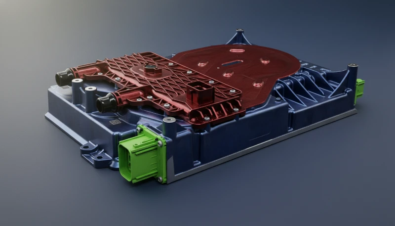
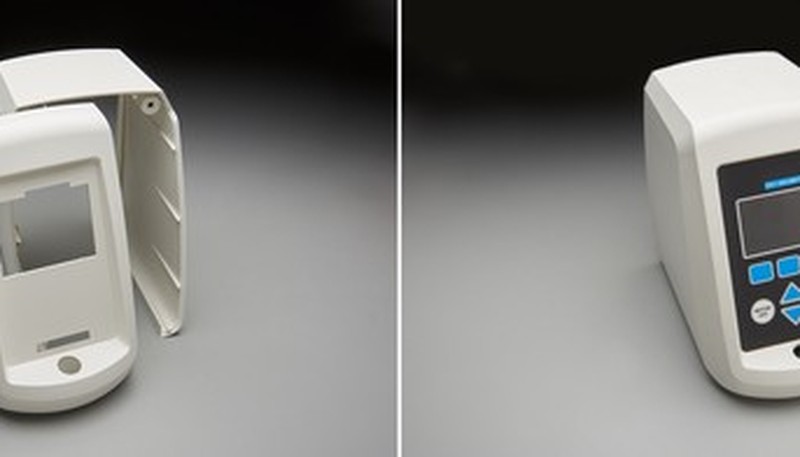
Automotive radar and ADAS sensors represent the fastest-growing segment: 77 GHz radar modules require SE above 60 dB from 76–81 GHz, driving adoption of nickel-coated CF compounds in underhood enclosures that must withstand –40°C to +125°C thermal cycling. These enclosures must also pass IP67 sealing requirements and maintain dimensional stability under continuous vibration loads. Medical devices such as MRI-compatible patient monitoring equipment and wireless infusion pumps require both EMI shielding and biocompatibility, typically achieved using PC/ABS blends with carbon fiber loading at 15% paired with USP Class VI tested base resins.
What Cost and Design Trade-offs Apply to EMI Shielded Enclosures?
Industrial IoT enclosures for smart factory sensors, motor drive housings, and power electronics represent a high-volume segment where cost optimization dominates: glass-fiber/carbon-black hybrid compounds at total loading of 25–35% achieve 25–35 dB SE at material cost 30–40% below pure carbon fiber grades. Consumer electronics—laptop chassis, gaming console shells, and wireless headset housings—increasingly use overmolding to combine a conductive inner shell with a cosmetic outer skin in a single manufacturing step, eliminating assembly and achieving class-A surface finish while maintaining 30–40 dB EMI attenuation. Defense and aerospace applications push the performance envelope further, requiring SE above 80 dB for electronic warfare and secure communications equipment, where specialized silver-coated polymer composites or metal-insert hybrid moldings are used alongside filled-resin structures.
Why Choose Injection Molding Over Sheet Metal for EMI Enclosures?
Across all these industries, the injection molding process offers a decisive advantage over sheet metal or die-cast housings: complex internal geometry—rib patterns, snap-fit features, boss structures, and integrated cable management channels—can be molded in a single shot at cycle times of 30–90 seconds per part. This integration of structural, functional, and EMI-shielding features in one step reduces bill-of-materials complexity and assembly labor by 40–60% in high-volume programs, making conductive injection molding the preferred choice when annual volumes exceed 10,000 parts. The repeatability of injection molding also ensures consistent shielding performance from the first part to the millionth, unlike hand-applied coatings that degrade in quality over time.
Frequently Asked Questions About EMI Shielding Injection Molding
What shielding effectiveness can I realistically expect from a conductive-filled injection-molded plastic part?
In production conditions, carbon-fiber-loaded compounds (15–30% CF) typically achieve 35–55 dB shielding effectiveness across 100 MHz to 3 GHz when wall thickness is at least 2.5 mm and weld lines are properly managed. Carbon-black grades (20–30%) deliver 20–30 dB, sufficient for FCC Class B compliance in many consumer electronics. Stainless steel fiber grades can reach 50–65 dB. However, real-world performance depends heavily on enclosure geometry, aperture design, seam design, and connector feedthrough treatment. Always validate with full enclosure SE testing rather than relying solely on material data sheet values, which are measured on flat plaques under ideal conditions.
How does wall thickness affect EMI shielding in injection-molded enclosures?
Wall thickness has a significant but non-linear effect on EMI shielding. Below 2.0 mm, the conductive fiber network becomes discontinuous, causing SE to drop sharply—often by 10–15 dB compared to 3.0 mm sections. Above 3.0 mm, additional thickness yields diminishing returns: going from 3 mm to 5 mm typically adds only 3–5 dB for carbon-fiber compounds. The practical sweet spot for most applications is 2.5–3.5 mm. Note that uniform wall thickness is more important than absolute thickness for shielding consistency—variation greater than 30% between sections creates conductivity discontinuities that can reduce local SE significantly.
Can I combine in-mold conductive coating with conductive-filled resin for higher shielding effectiveness?
Yes, this hybrid approach is used in high-performance applications such as 5G base station components and automotive radar modules where SE above 60 dB is required. The filled resin provides volumetric shielding (protecting even if the surface is abraded), while IMCC provides a uniform, low-resistance surface that enhances near-field shielding and shields aperture edges. In practice, combining 20% CF-loaded PA6 with a 30 μm IMCC nickel-paint layer achieves 55–70 dB SE, versus 40–50 dB for the resin alone. The cost premium is 20–35% per part but eliminates secondary spray operations entirely.
What are the key differences between carbon fiber, carbon black, and stainless steel fiber for EMI shielding?
Carbon black is the most cost-effective option—20–30% loading in PP or ABS achieves 20–30 dB SE and adds minimal cost premium—but it requires high loading levels that reduce impact strength and increase melt viscosity significantly. Carbon fiber at 15–30% delivers superior SE (35–55 dB) with better mechanical properties but is more expensive and can cause anisotropic shielding due to fiber orientation effects. Stainless steel fiber at 5–15% achieves 40–60 dB with the least mechanical property degradation among the three, but material cost is 4–6× carbon black. For most applications, carbon fiber provides the best balance of cost, SE performance, and processability.
How do I prevent weld lines from degrading EMI shielding performance?
Weld lines are unavoidable in many enclosure geometries, but their EMI impact can be controlled through three strategies. First, use mold flow analysis to predict weld line location and reposition gates to move them to non-critical faces—typically mounting flanges or rear panels away from antenna apertures. Second, specify minimum wall thickness of 2.5 mm at weld zones and consider local wall reinforcement if the weld line cannot be repositioned. Third, for critical applications, test a short-shot sample to confirm actual weld line location matches simulation, then adjust gate balance before full production. In our experience, these measures can recover 10–15 dB of SE lost to weld lines in a single design iteration.
Does EMI shielding affect the color and appearance of injection-molded plastic parts?
Most conductive fillers—carbon fiber, carbon black, and graphite—are black or dark gray, which limits color options to black, charcoal, and dark shades. Carbon black in particular produces a deep, uniform black with good surface quality. Stainless steel fiber can be compounded into lighter base resins, allowing dark gray and some medium-tone colors, but achieving white or bright colors with effective EMI shielding requires metallic flake additives or post-mold coating. For applications requiring specific RAL colors with EMI performance, IMCC (in-mold conductive coating) covered by a cosmetic top coat is typically the most effective approach, though it adds process steps and cost.
-
electromagnetic interference: Electromagnetic interference (EMI) is an undesired electrical disturbance generated by an external source that affects an electrical circuit, measured in dBμV/m across frequency ranges from 150 kHz to 30 GHz. ↩
-
conductive filler: Conductive filler refers to any additive—such as carbon black, carbon fiber, or metallic flakes—blended into a polymer matrix to reduce resistivity and enable EMI shielding effectiveness. ↩
-
surface resistivity: Surface resistivity is a material property measured in ohms per square (Ω/sq) that indicates how easily electric current flows across the surface of a conductive or semiconductive material. ↩
-
shielding effectiveness: Shielding effectiveness is a measure of how much an enclosure attenuates electromagnetic fields, defined as SE (dB) = 20 log10(E_incident / E_transmitted) for electric fields. ↩


