 Skip to content

Injection molding is an important manufacturing process used today to produce parts for a wide range of products. This process relies on runners and gates working together to ensure efficiency and high quality. Understanding these components is a must for anyone involved in injection molding, whether you’re a designer, mechanical engineer, or just a fan. In this blog post, we’re going to take a deep dive into the topic of runners and gates, exploring how they work, the different types, how they’re designed, and how they impact the overall injection molding process.

Runners
Runners in a mold injection process are the channels where the plastic material flows. The skills and craftsmanship in making the runners have great influence on some important factors such as the quality of the molding, the molding cycle, and the cost of the setup.

The runners serve as the main channels that carry the molten plastic from the nozzle of the injection molding machine. These runners are the transportation systems to the gate and serve as the paths for the molten plastics. They should be designed to be short and have fewer bends, so that they provide less resistance and less heat loss. The runners are usually designed to be triangular or circular in shape.
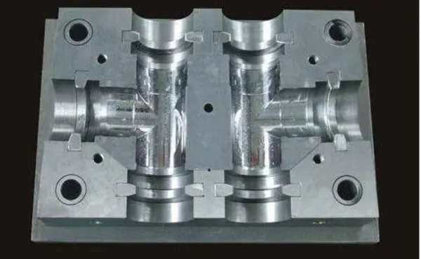
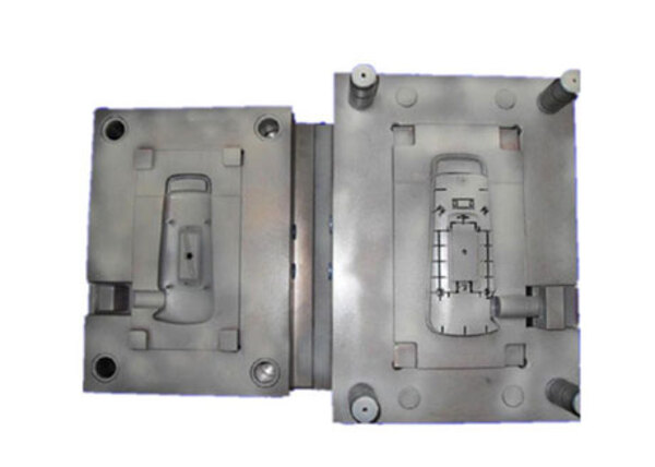
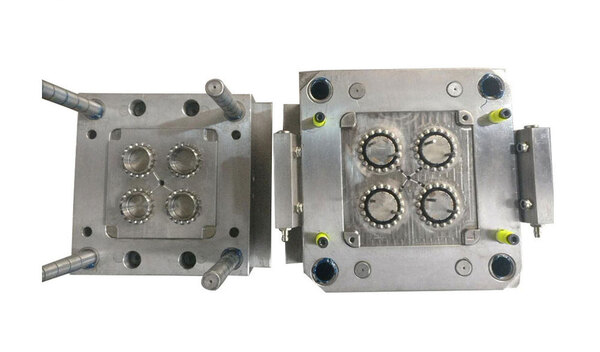
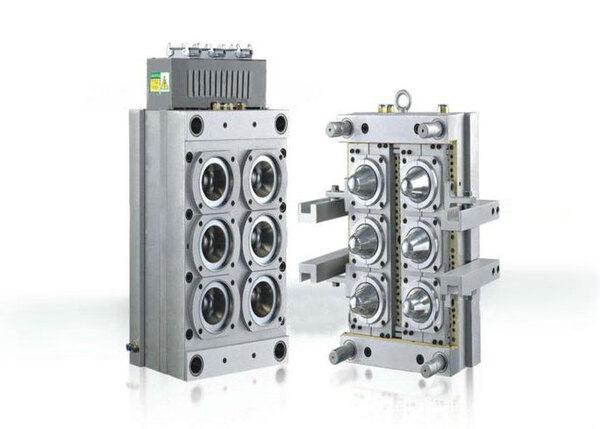
For molds with multiple cavities, the selection of the runners is important in order to achieve dimensional accuracy of the parts. The figure below shows a typical runner layout for a multi-cavity mold.

Classification of Runners
The runner design for plastic molds mainly includes linear, circular, point, and fan-shaped. Among them, linear and circular runners are the two most common types.
Linear runners are the molten plastic material flowing into the mold cavity through linear channels. They are characterized by their simplicity, easy to make, and high production efficiency. However, linear runners tend to leave dead spots, generate bubbles, and are not easy to eliminate break points, so they are not commonly used in high-precision products.
However, circular runners are different. They go all the way around the mold cavity with linear runners coming in from different directions. They have advantages. They make the plastic melt more uniform and make the pressure more even. But they are more complicated to design and to make. And they can cause problems. They don’t fit right. And they can make a sprue.

Principles of Runner Design
1. Avoid making too many twists and turns. These increase the defects and flow resistance that come with overly complicated part geometry and flow in plastics.
2. Use a shorter screw pull back so the injection cycle and mold fill time is reduced.
3. Taper the runner size as you go down the flow path to prevent air bubbles and maintain the flow of plastic.
4. Make sure the connection from the mold cavity to the runner is right for minimizing impacts and compressions as the polymer fills up, which will give you a better-looking surface and fewer defects.
Common Runner Types
1. Nozzle Type (Point) Runner
Nozzel-type runners use multiple nozzles connected to the mold cavity, forming tiny dots at the nozzel exits, suitable for making small or very fine plastic products.
2. Hot Runner
Hot runners heat the plastic up to a liquid state with heating pipes and then inject the plastic into the mold cavity through a nozzle. They effectively avoid problems like bubbles and shrinkage, making them suitable for producing high-precision plastic products.

3. Trench Runner
Trench runners are deep grooves machined into the die, with molten material fed to different cavities through branch pipes. They offer advantages such as short runner lengths and high smoothness, suitable for large, long, or thick-walled products.
4. Fan-shaped Runner
Fan-shaped runners divide the runner into multiple branches, each with a different angle. This ensures that molten material is evenly distributed to various cavities. It is suitable for producing multi-cavity plastic molding products.

Gates
When it comes to gate systems, the design is all-important. You need to decide where you’re going to put the gates, how many there’ll be, what they’re going to look like, and how big they’ll be. The main jobs of the gates are:
To control how much molten plastic gets into the mold cavity and where it goes.
To keep the plastic in the mold cavity and stop it going back up the runners before it’s gone hard.
To make some heat by squeezing the plastic and making it rub against itself.
To make it easy to get rid of the runners once the product’s gone hard and you don’t need them any more.
Classification
Injection mold gates are divided into non-restrictive gates and restrictive gates.
1. Non-restrictive Gate
The figure below shows non-restrictive gates, which are also called direct gates. This kind of gate has a simple mold design, easy operation, and molding, and reduces shrinkage. But this kind of gate increases the molding cycle time, and it is prone to molding defects such as cracks, warping and residual stress.

2. Restrictive Gate
Due to the small cross section, restrictive gates are usually designed to solidify quickly. The benefits of restrictive gates are:
① Less residual stress and deformation around the gate, reducing molding defects such as cracks, warping and deformation.
② Lower injection pressure inside the mold cavity, allowing a larger projected area of the product.
③ Faster gate closing time, reducing the molding cycle.
④ Better product quality by eliminating secondary processing.
Six Types of Restrictive Gates
① Side Gate
The thickness of a side gate is usually 30%-40% of the part wall thickness. Its width is about three times the part wall thickness. Side gates can be used with almost all plastics. Overlapping gates and spoke gates are variations of side gate designs.
② Fan Gate
Fan gates are used for flat products and have a wide, flat cross-section that effectively eliminates gate defects.

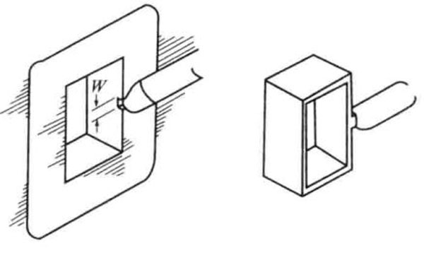
③ Film Gate
The image below shows a typical film gate design. It is the same width as the part but much thinner. Film gates, like fan gates, effectively eliminate part stress and part deformation.

④ Disk Gate
Thin disk gates are used to surround disk or ring-shaped parts to prevent weld lines from forming. A variation of the disk gate is the ring gate.

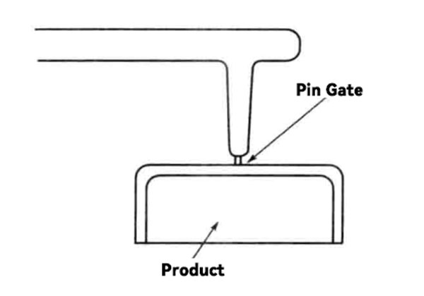
⑤ Pin Gate
Pin gates are usually located in the center of the part and are often used for multi-point gating. Because of their small diameter, usually 0.8-1.2mm, high flow resistance can occur. Low viscosity plastics or high injection pressures are recommended to avoid underfill.
Characteristics of Pin Gates:
- Less strict gate location selection
- Low residual stress around the gate
- Easier gate balance for multi-cavity molds
- For products with big projected areas, multiple pin gates effectively reduce product warping
- Pin gates are easy to trim, and for three-plate molds, automatic gate trimming is easily achieved, making
- Product and gate separation easy.
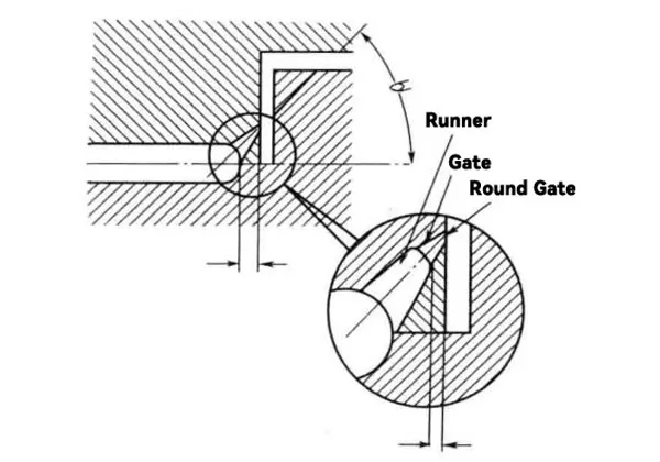
⑥ Submarine Gate
Here’s a picture of submarine gates. Normally, the gate is on the parting surface of the mold. While the runner is on the parting surface, the gate is usually on the moving or fixed plate of the mold and sometimes on the cavity. Although they’re like pin gates, the good thing about submarine gates is that you can even use them with two-plate molds. The gate automatically falls off when you eject the molded product.
Gate Balance
For multi-cavity molds, it’s important to get a uniform fill of molten plastic in each cavity. As the polymer pressure drops off as the plastic melt flows from the runner to the end of the cavity, gate balance should optimize the length, width, and depth of the gate.
Balanced gate and runner designs can prevent molding defects like flow marks, shrinkage, underfilling, dimensional fluctuations, and weight variations during actual molding.
Principles of Injection Mold Gate Design
1. The gate should be placed where it won’t leave marks or damage the important parts of the product.
2. Make the gate simple so the plastic flows smoothly and doesn’t make bubbles or leave holes.
3. Make the gate the right size for the product. If it’s too big, it’ll take too long to fill the mold. If it’s too small, you’ll have to use too much pressure to get the plastic into the mold.
4. The place where the gate meets the product should be as smooth as possible to keep from leaving marks and losing material when you trim it.
5. You want to use as few gates as possible because having multiple gates can cause the plastic to flow unevenly, which will make the parts come out different sizes.

Considerations
Basic factors to consider when positioning gates include part design, flow, and final product usage requirements. Remember the following points:
1. To make sure the pressure loss is as small as possible, the gate should be placed as close as possible to the large part. This will make the resin flow front intersection cool down less, resulting in a better weld line. The gate size should be chosen properly so that the resin can fill the mold with a reasonable pressure and velocity.
2. The transition length of the gate should be as short as possible.
3. The collision gate will help make the incoming fluid flow directly against the mold cavity wall or core, so as to avoid swirls.
4. To avoid getting air in the resin, make sure the air from the resin flow from the gate goes to the vent groove.
5. Put the gate where the resin can flow from the thick-walled areas to the thin-walled areas; keep the weld lines down; and stay away from the impact and stress areas.
6. To keep the swirls, radiated spots, and gate halos down, make sure the gate has the right angle with the runner.

7. If you gate right on the decorative surfaces, you can get surface defects.
Design Checks for Runners and Gates
(1) Is runner balancing required?
(2) Is the tip diameter of the gate matched with the diameter of the injection molding machine nozzle?
(3) Does the gate thickness meet flow requirements?
(4) Is the cross-sectional shape of the runner appropriate?
(5) What is the cross-sectional area of the runner?
(6) What is the average hydraulic radius of the runner?
(7) What is the weight of the runner?
(8) Is runner pulling required?
(9) Is the relationship between runner pulling and gate appropriate?
(10) Can the runner be smoothly demolded?
(11) Can the runner be smoothly ejected?
(12) What is the removal method of the runner? (Free fall, removal robot (direction))
(13) Is the gate position appropriate?
(14) Is the number of gates appropriate?
(15) Is the gate method appropriate?
(16) Can weld line occurrence positions be predicted?
(17) Can dimple occurrence positions be predicted?
(18) What is the gate cross-sectional size?

(19) Is the gate cutting method clear?
(20) Is quality management possible after gate cutting?
(21) What is the design life of the gate?
(22) Does the gate part need to be pre-divided into separate parts?
(23) Is the machining dimension measurement method of the gate part clear?
(24) What is the mold material of the gate part?
(25) What is the hardness of the gate part?
Conclusion
Runners and gates in injection molds are important for the injection molding process, but it’s important to know the difference between the two. Runners are winding channels that are used to guide the molten plastic from the injection machine into the mold cavity to form products. Gates are channels that go straight from the injection machine to the mold. They are used to melt the plastic pellets into the injection machine and then inject the molten material into the mold to form products. Proper runner design and gate control are important in injection molding to make sure the products are good quality and the production is efficient. They are necessary in the manufacturing of plastic products.
Also, injection mold design must consider gate and runner design. This includes product requirements, material characteristics, and injection molding process requirements to achieve the best product quality. In practical design, we should adjust and optimize based on actual conditions to continuously improve and enhance design proficiency.


