

If your molded PP part comes out 0.4 mm undersize on the first trial, shrinkage is usually the reason. Injection mold shrinkage is the predictable size reduction that happens as plastic cools, and good tooling teams design for it before steel is cut.
That sounds simple, but this is where many projects go sideways. Buyers often compare a tight drawing tolerance with a resin datasheet number and assume the mold should hit nominal on the first shot. In real production, resin family, wall thickness, gate balance, and process settings all change the final part dimension.
At ZetarMold, we treat shrinkage as a mold engineering problem, not a last-minute sampling surprise. During DFM, we combine material data, part geometry, and experience from similar tools so the first mold trial starts close to target instead of chasing corrections through repeated steel work.
- Injection mold shrinkage is calculated with S = [(Dm – Dp) / Dm] × 100.
- Typical shrinkage for molded plastics ranges from about 0.1% to 3.0%.
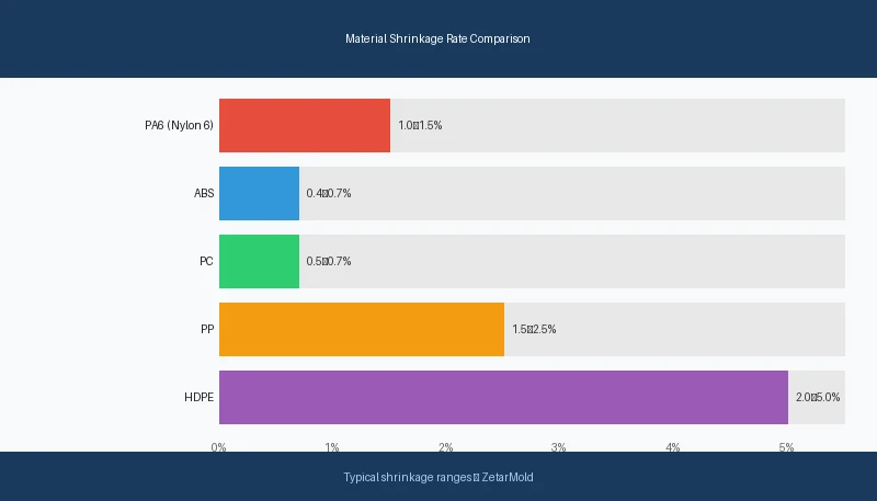
- Amorphous materials such as ABS, PC, and PMMA usually shrink less than semi-crystalline materials such as PP, PE, PA, and POM.
- Higher packing pressure, balanced wall thickness, and correct mold temperature all help reduce dimensional variation.
- Mold cavities are usually scaled by 1 plus the expected shrinkage factor, then fine-tuned after sampling.
What Is Injection Mold Shrinkage and Why Does It Matter?
Injection mold shrinkage is the dimensional reduction that occurs when molten plastic cools, solidifies, and relaxes after filling the cavity. It matters because the mold cavity is not the final size of the part; the cavity must be intentionally oversized to account for the way each resin contracts.
For most plastic parts, total shrinkage falls somewhere between 0.1% and 3.0%, but that range hides big differences between materials. A transparent PC cover may stay relatively stable, while a PP housing of the same size can move much more. That is why shrinkage is tied directly to both injection mold design and the broader injection molding process.
Two dimensions define the topic. Dm is the mold dimension, and Dp is the final part dimension after cooling. The gap between them is not waste or error by default. It is planned compensation, based on how the selected resin behaves during cooling and post-mold stabilization.
The biggest mistake is treating shrinkage as a single number pulled from a datasheet. Actual molded parts respond to local wall thickness, gate placement, cooling efficiency, and orientation. A flat plaque can shrink differently from a ribbed box, even when both are molded from the same resin lot on the same press.
This is also why warpage appears. When contraction is uniform, the part simply gets smaller. When contraction differs by direction or by section thickness, the part bends, twists, or pulls out of square. In practice, dimensional failure is often a differential cooling problem disguised as a tolerance problem.
“All injection molded materials shrink after molding.”True
Every thermoplastic loses volume as it cools from melt temperature to room temperature. The amount changes by resin family, filler content, and process conditions, but the basic contraction behavior is universal.
“You can use the same mold dimensions for both PP and ABS parts.”False
PP typically shrinks around 1.5-2.5%, while ABS is usually closer to 0.4-0.7%. A cavity sized for ABS will not hold the same final dimensions if the resin changes to PP.
At our Shanghai factory, shrinkage review starts before tooling release because cavity steel is expensive to rework later. We run 45 injection molding machines from 90T to 1850T, and the most common mismatch we see is a customer asking for ±0.05 mm on a semi-crystalline PP part, then questioning why T1 samples miss by 0.3-0.5 mm. That is usually inherent material behavior, not careless molding.
How to Calculate Mould Shrinkage: The Formula Explained
mould shrinkage1 is calculated with S = [(Dm – Dp) / Dm] × 100. In that formula, S is shrinkage percentage, Dm is the mold dimension, and Dp is the cooled part dimension measured after molding.
Here is the simple logic. Suppose the cavity dimension is 100.00 mm and the measured part is 98.50 mm after cooling. The calculation becomes S = [(100.00 – 98.50) / 100.00] × 100 = 1.5%. That means the part shrank 1.5% relative to the cavity size.
Engineers also run the equation in reverse during tool design. If the target part dimension is 100.00 mm and expected shrinkage is 1.8%, the cavity should be about 101.80 mm before steel is cut. In other words, mold dimensions are scaled by 1 plus the shrinkage factor, then validated through sampling.
That reverse calculation is practical, but it still needs judgment. Datasheet values are often given as a range because the same resin can behave differently under different injection molding process parameters. Packing profile, cooling time, gate freeze, and mold surface temperature all influence where the finished part lands inside that range.
For accurate measurement, do not rush dimensional inspection the moment the part is ejected. Many materials continue to relax after demolding, especially thick-walled or semi-crystalline grades. A consistent inspection method matters as much as the formula itself. If one team measures after 10 minutes and another measures after 24 hours, the shrinkage result may not be comparable.
A good process study separates overall shrinkage from local variation. A box may show acceptable outer dimensions but still fail around holes, bosses, or ribs because those sections cool at different rates. That is why experienced tooling teams measure several control dimensions instead of relying on one overall length.
In production tooling, we normally start with the supplier’s material range, compare it against similar historical tools, and then set sampling checkpoints around the most sensitive dimensions. If the part is cosmetic or functional, we may prioritize one dimension for steel-safe tuning while leaving other areas adjustable through process optimization.

Shrinkage Rates by Material: Semi-Crystalline vs. Amorphous
Material family is the biggest driver of shrinkage, and semi-crystalline resins usually shrink more than amorphous ones. As a rule, amorphous materials such as PC, ABS, and PMMA often fall around 0.4-0.8%, while semi-crystalline materials such as PP, PE, PA, and POM more often land between 1.0% and 3.0% or even higher in some grades.
The reason is structure. During cooling, amorphous plastics freeze in a more random molecular arrangement, so volume change is relatively limited and more uniform. A thermoplastic with a semi-crystalline2 structure forms ordered regions as it cools, which increases contraction and can make the shrinkage more directional.
Directional behavior matters even more with reinforced grades. Glass-filled nylon, for example, can shrink one way along the flow path and another way across it. That anisotropic response is a classic source of injection mold design challenges because bosses, ribs, and flat panels do not all react the same way once fiber orientation is introduced.
| Material | Type | Shrinkage Rate | Typical Use |
|---|---|---|---|
| PP | Semi-crystalline | 1.5-2.5% | Consumer goods, auto parts |
| PE (HDPE) | Semi-crystalline | 1.5-3.0% | Containers, packaging |
| PA66 (Nylon) | Semi-crystalline | 1.0-2.0% | Mechanical parts |
| POM (Acetal) | Semi-crystalline | 2.0-3.5% | Precision gears |
| ABS | Amorphous | 0.4-0.7% | Electronic enclosures |
| PC | Amorphous | 0.5-0.7% | Optical parts, safety |
| PMMA | Amorphous | 0.2-0.5% | Displays, lenses |
The table shows why a resin switch is never trivial. If a customer changes from ABS to PP to reduce cost, the tooling team has to revisit cavity sizing, gate balance, and tolerance assumptions. The part may still look similar, but the dimensional behavior can shift enough to require steel changes or at least a new process window.
“Higher 3 reduces shrinkage.”True
Higher packing pressure pushes more molten material into the cavity before the gate freezes. That extra mass offsets volumetric contraction during cooling and usually improves final dimensions.
“Shrinkage is the same in all directions for all plastics.”False
Many materials, especially glass-filled grades, shrink differently in flow and cross-flow directions. In reinforced nylons, cross-flow shrinkage can be 30-50% higher than flow-direction shrinkage.
This is why material review has to happen early. A mold that runs beautifully in ABS can become unstable in POM or PA without redesigning cooling and gating strategy. Material cost is visible on the quote, but the hidden cost often shows up later as tool tuning, slower cycle time, and extra dimensional inspection. In tooling reviews, we compare resin change requests against the original cavity strategy because a low-cost material substitution can create expensive dimensional instability. What looks like a simple procurement choice may require a different gate size, revised cooling, or extra steel-safe stock on critical fit features. That is one reason experienced molders challenge late material changes instead of treating them as harmless.
7 Factors That Affect Injection Mold Shrinkage
Injection mold shrinkage is affected most by material type, wall thickness, packing pressure, mold temperature, melt temperature, gate location, and part geometry. Those seven variables decide how much material enters the cavity, how evenly it cools, and whether the contraction stays uniform or turns into warpage.
1) Material type sets the baseline. Semi-crystalline resins naturally shrink more than amorphous grades, and filler content changes the pattern further. A 30% glass-filled PA behaves nothing like unfilled PP, even if the nominal part size is the same.
2) Wall thickness controls cooling speed and local mass. Thick zones stay hot longer, keep shrinking longer, and are more likely to pull sinks or distort nearby surfaces. Thin and thick transitions are especially risky because the part is being asked to cool at two different rates at the same time.
3) packing pressure directly compensates for volume loss before the gate freezes. In many tools, the effective packing range is around 60-80% of injection pressure. Too little hold pressure leaves the cavity under-packed. Too much can flash the part or create stress that shows up later as dimensional drift.
4) Mold temperature changes how quickly the polymer solidifies at the cavity wall. Higher mold temperatures can improve surface finish and flow, but they often allow more crystallization in semi-crystalline resins, which can raise shrinkage. Lower temperatures may reduce total shrinkage but increase frozen-in stress if cooling is too aggressive.
5) Melt temperature changes the material’s starting point. Hotter melt usually flows better into thin sections, but it also increases the amount of heat that must be removed from the part. If cooling and packing are not adjusted with it, final dimensions can move unexpectedly.
6) Gate location decides the flow path and pressure distribution. A poorly placed gate causes uneven fill, uneven pack, and uneven orientation. On larger parts, that is one of the fastest ways to create opposite corners that shrink by different amounts.
7) Part geometry amplifies everything else. Flat panels, long ribs, isolated bosses, and asymmetrical walls all make cooling less balanced. This is where shrinkage stops being just a resin issue and becomes a full tool engineering issue tied to injection molding materials, cooling layout, and feature design.
| Factor | Typical effect | Best response |
|---|---|---|
| Higher wall thickness | Raises local shrinkage risk | Core out heavy sections |
| Higher packing pressure | Reduces overall shrinkage | Tune hold profile before freeze |
| Uneven gate location | Raises directional variation | Move or rebalance gates |
When these variables are not balanced, the result is often differential shrinkage4 rather than simple overall size loss. Flow direction can contract differently from cross-flow direction, especially in glass-filled materials. That uneven contraction leads directly to warpage, bowed walls, twisted frames, and tolerance failures at assembly interfaces.
The practical lesson is that no single parameter can rescue a poor geometry decision. If the part has thick ribs feeding a large flat wall and the gate is at one end, you cannot always solve the problem by raising hold pressure alone. The better fix may be changing rib ratio, relocating the gate, or redesigning cooling around the hot spot.
How to Compensate for Shrinkage in Mold Design
Shrinkage is compensated in mold design by scaling cavity dimensions above the target part size and then supporting that sizing with balanced gating, cooling, and steel-safe tuning. The simple rule is to multiply the target dimension by 1 plus the expected shrinkage factor.
For example, if the required finished width is 80.00 mm and expected shrinkage is 1.2%, the starting cavity width becomes 80.96 mm. That gives the toolmaker a realistic first-cut dimension. From there, T1 and T2 trials tell you whether the real resin lot, actual cooling line layout, and part geometry confirm the estimate or push it slightly higher or lower.
Good compensation is never just a spreadsheet exercise. Mold designers also choose gate positions that pack the critical areas first, size runners to maintain pressure, and build cooling lines so the hottest zones do not lag far behind the rest of the cavity. On tighter parts, steel-safe dimensions are planned intentionally so post-sampling adjustments stay possible.
Material-specific planning matters here. If a project uses PP, PE, PA, or POM, we assume more dimensional movement and review tolerance feasibility early. On tools using lower-shrink materials like ABS or PC, the cavity may need less compensation, but dimensional consistency can still be lost if ejection, cooling balance, or venting are weak.
We also separate global compensation from local compensation. A housing may need one overall scale factor, but bosses around screws or alignment tabs may need localized steel changes after trials. That is normal. The goal is not to guess perfectly once. The goal is to make the first mold version intelligent enough that tuning is small, fast, and predictable.
In DFM reviews, we often flag designs where tolerance expectations are tighter than the selected material can realistically support. If a buyer wants a large PP cover to hold near-machined tolerances, the better engineering answer may be to change the material, add assembly float, or convert one critical feature into a post-machined surface rather than force the entire part into an unstable process window.
Common Shrinkage Problems and How to Fix Them
The most common shrinkage problems are undersize parts, sink marks, warpage, oval holes, and dimension-to-dimension inconsistency. Each problem points to a different combination of root causes, so the fix starts with reading the pattern instead of changing settings blindly.
If the entire part is uniformly undersize, the first suspect is incorrect shrinkage allowance in the tool. That usually means the cavity scale factor was too low or the actual material shrinkage is above the datasheet midpoint. The fix may require steel correction, but first confirm that the pack profile and measurement timing are consistent.
If sinks appear above ribs or bosses, the issue is usually local mass concentration. A thicker interior feature keeps shrinking after the skin has frozen, pulling the outer surface inward. Common fixes include reducing rib thickness, increasing hold time, improving gate efficiency, or moving the gate closer to the heavy section so the cavity remains packed longer.
“Uniform wall thickness improves shrinkage control.”True
When wall thickness stays more consistent, cooling becomes more balanced and the part is less likely to develop sinks, warpage, or local dimensional drift.
“More cooling time always fixes shrinkage problems.”False
Longer cooling can stabilize some parts, but it cannot correct poor gate placement, incorrect cavity compensation, or severe thick-to-thin geometry transitions by itself.
If the part bows or twists, treat it as a warpage problem caused by unequal shrinkage. Look for asymmetric wall sections, weak cooling around one side, or material orientation from a one-sided gate. Process changes may help, but if the shape itself drives uneven cooling, the long-term correction usually lives in the tool or the part design.
If round holes become oval or mating tabs stop lining up, check for flow-direction effects. Reinforced materials can show strong orientation, and even unfilled resins may shift around long flow paths. In those cases, a gate relocation or a modified cooling layout often works better than simply increasing pressure.
If dimensions vary from cavity to cavity, compare actual cooling circuit performance, venting, and gate balance before blaming the resin. Multi-cavity molds amplify small differences. One cavity running 3°C hotter than the others can create a dimensional trend that looks random until you map it against the tool layout.
The worst response is shotgun tuning. Raising injection pressure, lowering mold temperature, and extending cooling all at once may shift the result, but it also hides the root cause. A better method is to lock one parameter set, change one variable at a time, and record how each critical dimension moves. That turns debugging into data instead of guesswork.
ZetarMold’s Approach to Shrinkage Control
ZetarMold controls shrinkage by combining DFM review, realistic material selection, steel-safe tooling, and measured sampling feedback. We do not treat shrinkage as a generic number; we treat it as a predictable manufacturing behavior that must be engineered into the tool from the first design review.
Our first step is material and tolerance alignment. If the drawing asks for a very tight tolerance on a large semi-crystalline part, we raise that issue early instead of pretending the mold can solve everything later. That conversation often saves more time than any tool adjustment, because it resets the project around material reality rather than wishful nominal dimensions.
Next, we review part geometry for the classic shrinkage traps: thick-to-thin transitions, isolated bosses, long unsupported walls, and gates that create one-way flow through the most critical dimensions. We then use that review to recommend gate changes, cooling changes, or steel-safe stock on sensitive areas before manufacturing starts.
During mold trials, we measure the dimensions that matter most to fit and function, not just the easiest dimensions to inspect. If the part needs later tuning, we want the tuning to happen in controlled, reversible steps. That is why our sampling reports track actual dimensional movement against process settings instead of just listing pass or fail.
The short version is simple: if shrinkage is reviewed at the DFM stage, most dimensional issues can be predicted, compensated, or at least contained. If shrinkage is ignored until first shots, the project usually pays for it in extra trials, mold rework, and slower launch timing.
FAQ: Frequently Asked Questions About Mould Shrinkage?
What is a normal shrinkage rate in injection molding?
A normal shrinkage rate is roughly 0.1% to 3.0%, depending on resin family, filler content, wall thickness, and processing conditions. Amorphous materials such as ABS and PC are often below 1.0%, while semi-crystalline materials such as PP, PE, PA, and POM often exceed 1.0% and can approach or pass 3.0% in some applications. The right number for tooling should come from both the datasheet and real molding experience with similar part geometry, not from a generic average alone. This is why engineers validate shrinkage with actual molded samples before approving final production dimensions.
Why does PP shrink more than ABS?
PP usually shrinks more than ABS because PP is semi-crystalline and forms ordered regions during cooling, which increases volume contraction. ABS is amorphous, so its molecular structure freezes more randomly and tends to produce lower, more uniform dimensional change after molding. In practice, that difference changes how much the cavity must be oversized and how tightly the process must control cooling and packing if the final dimensions are critical. This is why engineers validate shrinkage with actual molded samples before approving final production dimensions.
How do you reduce shrinkage in injection molding?
You reduce shrinkage by selecting the right material, keeping wall thickness more uniform, applying adequate hold pressure, balancing cooling, and sizing the cavity correctly from the start. In many tools, optimizing packing pressure and gate efficiency delivers the fastest improvement because more material is packed in before freeze-off. Reducing local mass around ribs and bosses also helps, because thick sections continue shrinking after the outer skin has already solidified. This is why engineers validate shrinkage with actual molded samples before approving final production dimensions.
Can shrinkage cause warpage?
Yes, shrinkage causes warpage when it is not uniform across the part. If one side cools faster, one direction shrinks more, or one feature remains hot longer, the part bends or twists instead of shrinking evenly. That is why warpage is usually a differential shrinkage problem, not just a simple size problem. Reinforced materials are especially sensitive because fiber orientation can make flow-direction and cross-flow contraction behave very differently. This is why engineers validate shrinkage with actual molded samples before approving final production dimensions.
When should shrinkage be considered during mold development?
Shrinkage should be considered before mold steel is cut, ideally during DFM and gating review. Once the cavity is machined, correcting a wrong shrinkage assumption becomes much more expensive because the team may need steel welding, machining changes, or repeated sampling to recover the target dimensions. Early planning also helps confirm whether the selected resin can realistically hold the drawing tolerance without forcing the process into an unstable or inefficient production window. This is why engineers validate shrinkage with actual molded samples before approving final production dimensions.
What is the difference between overall shrinkage and differential shrinkage?
Overall shrinkage is the general size reduction of the whole part after cooling, while differential shrinkage is uneven contraction between areas or directions of the same part. Overall shrinkage mainly changes size. Differential shrinkage changes shape and often causes warpage, bowed walls, or misalignment in assembly features. Engineers watch for differential shrinkage closely in glass-filled materials, long-flow parts, and parts with uneven wall thickness because those designs are much more likely to distort. That distinction matters because one issue is solved by cavity scaling, while the other often needs design or cooling changes.
-
mould shrinkage: Mould shrinkage is a volumetric reduction of a plastic part as it cools from the melt temperature to room temperature inside the mold cavity, measured as a percentage of the original mold dimension. ↩
-
semi-crystalline: Semi-crystalline refers to a polymer structure that contains both ordered crystalline regions and disordered amorphous regions, resulting in higher shrinkage and anisotropic behavior during cooling. ↩
-
packing pressure: Packing pressure is a secondary injection pressure applied after the mold cavity is filled, measured as a percentage of injection pressure, typically 60-80%, used to compensate for shrinkage as the plastic cools. ↩
-
differential shrinkage: Differential shrinkage refers to unequal shrinkage in different directions of a molded part, most pronounced in glass-fiber-reinforced materials where flow direction shrinkage differs from cross-flow shrinkage by up to 50%. ↩


