 콘텐츠로 건너뛰기

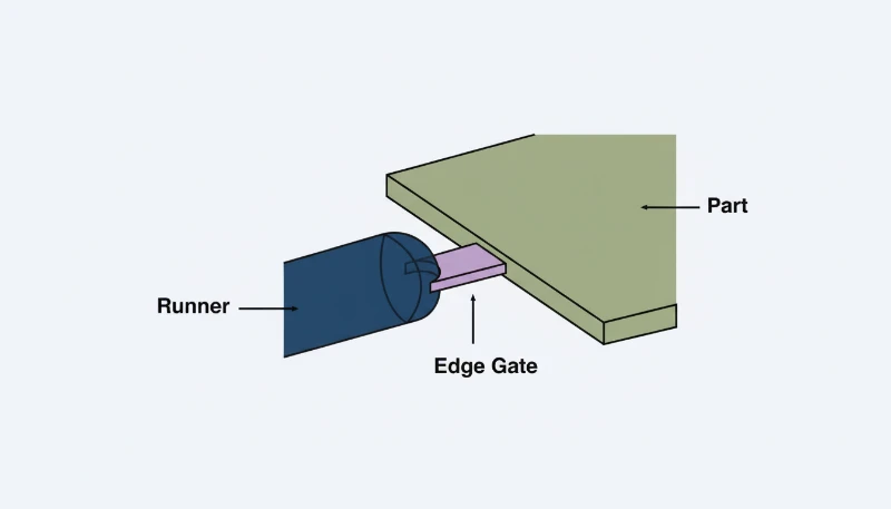
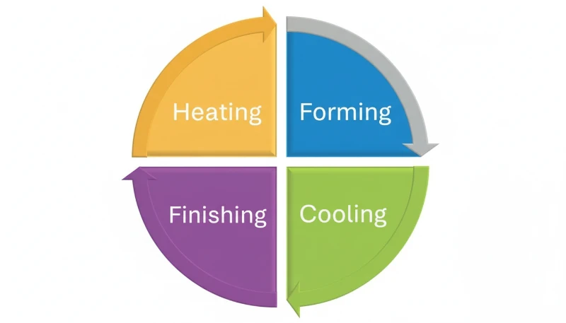
에지 게이트 설계는 용융 흐름을 캐비티 벽면을 따라 유도합니다
– The primary fix is reducing injection speed during the initial fill phase to 10–30% of normal speed, then ramping up once the melt contacts the opposite cavity wall.
– Gate design is the most important mold factor—switching from a pinpoint gate to a fan gate or tab gate eliminates jetting at the source.
– Increasing melt temperature by 10–20°C reduces material viscosity and promotes smoother flow entry into the cavity.
What Is Jetting in Injection Molding?
Jetting is a surface defect where molten plastic enters the mold cavity as a narrow, high-velocity jet instead of spreading out in a smooth, expanding melt front. The result is a distinctive snake-like or worm-track pattern on the part surface, usually visible near the gate area. In our factory, jetting is one of the most recognizable defects—once you’ve seen it, you never mistake it for anything else.
The jet of plastic flies across the cavity and folds back on itself as it piles up against the opposite wall. Because the jetted material has partially cooled during its flight, it doesn’t fuse properly with the material that fills in around it. This creates visible lines, rough texture, and potentially weak spots where the jetted stream meets the bulk fill.
What Causes Jetting to Occur?
Jetting happens when the 사출 속도1 is too high relative to the gate geometry, causing the melt to squirt through the gate rather than flow against the nearest cavity wall. We’ve identified several specific conditions that create jetting.
| 원인 | Mechanism | Likelihood |
|---|---|---|
| Excessive initial injection speed | Melt accelerates through the gate and becomes a free jet | 매우 높음 |
| Small gate with large cavity behind it | High velocity through small orifice with no wall to redirect flow | 높음 |
| Gate facing open cavity (not a wall) | No nearby surface to contact and start fountain flow | 높음 |
| Low melt temperature | Higher viscosity increases jet velocity through the gate | Medium |
| Cold slug in nozzle | Solid slug pushes through gate, followed by high-velocity melt | Medium |
| Sharp gate edges | Abrupt transition creates a nozzle effect that accelerates the melt | Medium |
The single most common cause we see is a small gate (pinpoint or submarine) directing melt into a large open cavity with no opposing wall nearby. The melt has nowhere to contact and spread—so it jets.
“Jetting is purely a cosmetic defect and has no effect on part strength.”False
While jetting is highly visible as a surface defect, the jetted material doesn’t fuse well with surrounding material because it has partially cooled during free flight. This creates weak boundaries within the part, potentially reducing impact strength by 20–40% in the affected area. Parts with severe jetting can fail under stress at the jet-to-bulk interface.
“Reducing the initial injection speed is the fastest and most effective process fix for jetting.”True
By slowing the injection speed to 10–30% of normal during the first 5–15% of cavity fill, the melt enters gently enough to contact the nearest cavity wall and establish proper fountain flow. Once fountain flow is established, speed can be ramped up to normal for the remainder of the fill.
How Do You Adjust Process Parameters to Prevent Jetting?
Process adjustments are the first line of defense against jetting because they don’t require mold modifications. We’ve developed a proven sequence that resolves jetting in 80% of cases through machine settings alone.
1. Use Multi-Stage Injection Speed: This is the most effective fix. Set the first stage (0–15% of fill) to 10–30% of normal injection speed. Once the melt has established contact with the cavity wall and formed proper fountain flow2, ramp up to full speed for the remaining fill.
2. Increase Melt Temperature: Raise barrel temperature by 10–20°C. Lower viscosity at higher temperature means the melt is less likely to form a coherent jet—it spreads out more readily on entering the cavity.
3. Increase Mold Temperature: Raise mold temperature by 10–15°C. A warmer mold surface helps the melt spread instead of solidifying on contact, promoting adhesion between the initial jet (if any) and subsequent fill.
4. Reduce Holding Pressure Switch Position: If you’re switching from injection to holding pressure too late, the melt is still being injected at high velocity when jetting occurs. Adjust the V/P switchover point to reduce the high-speed fill phase.
5. Ensure Proper Nozzle Temperature: A cold nozzle can create a cold slug that blocks the gate, then breaks free as a projectile followed by high-velocity melt. Maintain nozzle temperature at or slightly above barrel temperature.
What Gate Design Changes Eliminate Jetting?
If process adjustments don’t fully resolve jetting, gate design is almost always the root cause. The right gate design prevents jetting by directing the melt against a cavity wall immediately upon entry, establishing fountain flow from the start.
| 게이트 유형 | 시뮬레이션 소프트웨어로 제팅을 예측할 수 있나요? | 왜 | 최상의 대상 |
|---|---|---|---|
| Pinpoint Gate | 높음 | Small orifice creates high-velocity jet | Small parts (use with slow initial speed) |
| 잠수함 게이트 | 중간-높음 | Below parting line, often into open cavity | Auto-degating (requires speed profiling) |
| 엣지 게이트 | 낮음 | Melt directed along cavity wall | Most applications |
| Fan Gate | Very Low | Wide entry spreads melt across cavity | Flat parts, panels |
| Tab Gate | Very Low | Sacrificial tab absorbs initial jet | Parts with high cosmetic requirements |
| Cashew Gate | Medium | Curved path reduces velocity | Auto-degating with reduced jetting |
The most reliable anti-jetting gate design is one where the melt enters the cavity and immediately hits an opposing wall within 2–3 mm. This forces the melt to spread out and establish fountain flow. When we design new molds for jetting-prone geometries, we always specify gate orientation toward the nearest cavity wall.
“Increasing the injection speed helps solve jetting because it forces the melt to fill faster.”False
Increasing injection speed makes jetting worse, not better. Jetting is caused by excessive melt velocity through the gate. The correct approach is to decrease the initial injection speed to allow the melt to contact the cavity wall and establish fountain flow before ramping up speed for the remainder of the fill.
“A tab gate or fan gate design virtually eliminates jetting by spreading the melt entry across a wider area.”True
Fan gates and tab gates distribute the melt across a wider cross-section, dramatically reducing the local velocity at the gate entry point. Fan gates spread melt across the full part width, while tab gates absorb the initial high-velocity jet in a sacrificial tab that is trimmed after molding.
What Role Does Material Choice Play in Jetting?
Material viscosity and flow characteristics significantly influence jetting tendency. In our experience, lower-viscosity materials are more prone to jetting because they flow more easily through small gate openings at high velocity.
- High jetting risk: Nylon (PA), PP, PE—low viscosity materials that flow easily through small gates.
- Medium jetting risk: ABS, PS—moderate viscosity, jetting occurs with pinpoint gates at high speed.
- Lower jetting risk: PC, PMMA, PVC—higher viscosity resists free-jet formation, but jetting still possible with extreme speeds.
For low-viscosity materials like PA and PP, we always recommend either fan/tab gates or multi-stage injection speed profiles. The combination of easy-flowing material and a small gate is almost guaranteed to produce jetting without proper speed control.
How Do You Verify That Jetting Has Been Eliminated?
After making adjustments, we use a systematic verification process to confirm jetting has been fully resolved and won’t return under normal production variations.
- Visual inspection: Examine 20 consecutive shots under bright light at a 45° angle. Flow marks and jetting patterns are most visible under oblique lighting.
- Short-shot study: Intentionally short-fill the part at 30%, 50%, 70%, and 90% to observe how the melt front advances. Proper fountain flow shows a smooth, expanding front—jetting shows a worm-like pattern.
- Process window verification: Vary injection speed ±10% and melt temperature ±5°C from your optimized settings. If jetting reappears within this window, the process is not robust enough and further gate or parameter adjustments are needed.
- Cross-section analysis: Cut a part through the gate area and polish the cross-section. Under magnification, jetted material shows distinct flow boundaries with the surrounding fill material.
자주 묻는 질문
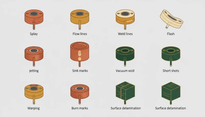
What is the difference between jetting and flow marks?
Jetting creates a distinctive snake-like or worm-track pattern near the gate, caused by free-stream injection of melt into the cavity. Flow marks are wavy ripple patterns across the part surface, caused by uneven cooling of the melt front. Jetting is fixed by slowing initial injection speed; flow marks are fixed by increasing speed and temperature.
Can jetting occur with hot runner systems?
Yes. Hot runner systems can still produce jetting if the gate size is too small and the injection speed is too high. However, hot runners with valve gates offer excellent jetting control because the valve pin controls exactly when and how fast the gate opens.
Is jetting more common in thin-wall or thick-wall parts?
Jetting is more common in thick-wall parts where the gate opens into a large, open cavity. In thin-wall parts, the melt is forced to flow between closely spaced walls, which naturally establishes fountain flow and suppresses jetting.
Can simulation software predict jetting?
사출 성형에서 제팅 현상을 방지하는 방법 | ZetarMold 금형 흐름 분석3 software like Moldflow and Moldex3D can predict jetting by analyzing the velocity profile at the gate and the melt front advancement pattern. We run simulations on all new mold designs to identify and prevent jetting before cutting steel.
How long does it take to fix jetting in production?
Process adjustments (speed profiling, temperature changes) can be implemented and verified in 30–60 minutes. Gate modifications require mold changes that typically take 1–3 days for welding and re-machining. A complete gate redesign may require 1–2 weeks for new insert fabrication.
Does jetting affect the recyclability of parts?
No. Jetting doesn’t change the material chemistry, so jetted parts can be ground and recycled normally. However, severely jetted parts may be rejected for quality reasons, increasing scrap rates and effectively increasing material waste.
요약

Jetting in injection molding is a predictable and preventable defect. The fastest fix is implementing multi-stage injection speed profiling—slow initial fill (10–30% speed) to establish fountain flow, then ramp to full speed. For a permanent solution, gate design is critical: fan gates, tab gates, and edge gates directed toward a cavity wall virtually eliminate jetting risk. In our factory, we’ve resolved every jetting case we’ve encountered through a combination of these process and design approaches. The key is recognizing that jetting is fundamentally a gate-velocity problem—control the melt’s entry behavior, and the defect disappears.
-
Injection speed is the rate at which the injection screw pushes molten plastic into the mold cavity, measured in mm/s or cm³/s. In the context of jetting, the initial injection speed (first 5–15% of fill) is the critical parameter—it determines whether the melt enters as a controlled flow or an uncontrolled jet. ↩
-
Fountain flow is the desired flow pattern in injection molding where the melt front advances as a smooth, expanding arc that contacts the mold walls on both sides. The leading edge of the melt continuously unfolds outward (like a fountain), creating a uniform flow front. Jetting occurs when fountain flow fails to establish. ↩
-
Mold flow analysis is a computer simulation technique that predicts how molten plastic will fill a mold cavity, using finite element analysis to model pressure, temperature, velocity, and shear stress throughout the filling, packing, and cooling phases. It enables engineers to identify defects like jetting before manufacturing the mold. ↩


