 コンテンツへスキップ

- リブ厚はノミナルウォール厚の40~60%とすべきです
- 不適切なリブ設計は、流動の遅れとシンクマークを引き起こします
- ベース半径と抜き勾配は、金型内の流動と冷却効率の両方に影響します
- 構造用途では、単一の高いリブよりも複数の薄いリブの方が性能が優れています
- Moldflowシミュレーションは、金型製作前にリブの欠陥を予測できます
リブ設計は射出成形部品設計において最も重要な決定事項の一つです。適切に設計されたリブ構造は、肉厚を増やすことなく剛性を向上させ、重量やコストを抑えることができます。しかし、形状を誤ると、 flow hesitation1, シンク跡2、そして金型の寿命にわたる冷却の遅延を引き起こします。月に数百セットの金型で生産を実行してきた経験から、リブに関連する欠陥は初品検査で部品が不合格となる上位5つの理由の一つです。プロセスのより広い視点については、当社の injection molding complete guide 材料選択から生産最適化まで全てを網羅しています。
この記事では、リブの形状(肉厚、高さ、抜き勾配、ベース半径、間隔)が、キャビティ内の溶融プラスチックの流動挙動と完成部品の冷却効率の両方をどのように直接決定するかを検証します。新しい射出成形部品を設計している場合でも、既存の金型の欠陥をトラブルシューティングしている場合でも、これらの関係を理解することは、一貫した部品品質とコスト効率の高い生産サイクルを実現するために不可欠です。
射出成形におけるリブとは何か、そしてなぜ重要なのか?
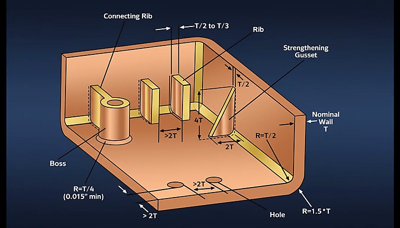
リブは、射出成形部品の公称壁から垂直に突き出た薄いブレード状の構造要素です。その主な目的は、肉厚、材料使用量、サイクルタイムを比例的に増加させることなく、曲げ剛性と剛性を高めることです。金型流動の観点では、リブは補助流路として機能します:公称肉厚に対するリブの厚みに応じて、溶融樹脂を部品全体に均一に分布させる役割を果たすこともあれば、溶融フロントの停滞や凍結を引き起こすこともあります。冷却に関しては、リブと壁が交わるT字接合部は局所的な熱容量を形成し、周囲の鋼材よりも冷却が遅くなるため、リブの反対側の外観面にシンクマークが生じます。
If you are comparing vendors or planning procurement, our injection molding supplier sourcing guide covers RFQ prep, qualification, and commercial risk checks.
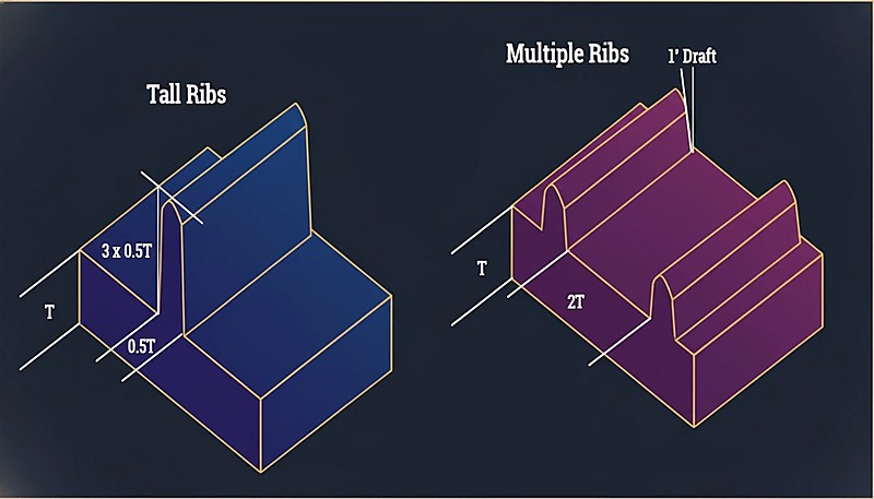
基本的な緊張関係は単純です:リブを薄すぎると射出時に適切に充填されず、厚すぎると交差部分が熱貯留層となり、シンクマーク、ボイド、サイクル時間の延長を引き起こします。業界の合意範囲であるノミナルウォール厚の40%から60%は、両方の懸念をバランスさせています。当社の上海工場では、剛性目標を達成するために60%を超えて設計したエンジニアが、品質チームからシンクマークによる不合格判定を必ず受ける様子を直接目撃してきました。正しいアプローチは、単一の厚いリブではなく複数の薄いリブを使用することです。この戦略は剛性を維持しながら、各交差部分の熱容量を管理可能な範囲に保ちます。
「理想的には、外観不良を防ぐために、リブ肉厚は隣接する公称肉厚の40%から60%の間に維持すべきです。」真
リブを主壁よりも薄く保つことで、交差部での過剰な材料蓄積を防ぎ、外観面でのシンクマークやボイドのリスクを大幅に低減できます。
「リブをメインウォールと同じ肉厚にすることが、副作用なしに部品強度を最大限に高める最良の方法です。」偽
均一な肉厚は交差点に大きな質量を作り、深刻なシンクマーク、内部ボイド、およびベースでの熱保持による冷却時間の大幅な増加を引き起こします。
リブ設計最適化のための主要パラメータは何か?
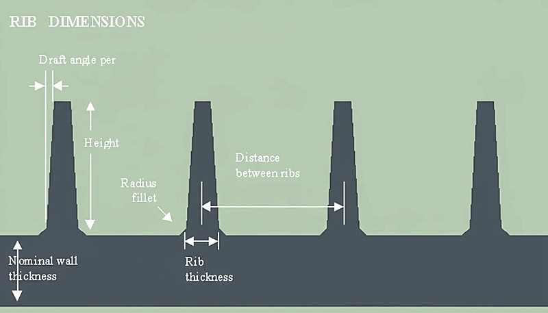
重要なパラメータは、リブ厚、高さ、抜き勾配、基部半径、間隔です。それぞれが独立して、メルトがキャビティ内を流れる方法と、金型から熱を効率的に取り除く方法に影響を与えます。これらのうち一つでも間違えると、充填不良、寸法不安定性、外観不良が連鎖的に発生し、高価な金型改造が必要になる可能性があります。以下の表は、各パラメータ、その推奨範囲、および流動と冷却への二重の影響をまとめたものです。
| パラメータ | 推奨値 | Impact on Mold Flow | Impact on Cooling |
|---|---|---|---|
| Rib Thickness (t) | 40% – 60% of Nominal Wall (T) | 薄いリブは流動の遅れを引き起こし、厚いリブは充填を改善しますが欠陥のリスクがあります | 厚いリブは局所的な質量を増加させ、シンクマークを防ぐために長い冷却時間を必要とします |
| Rib Height (H) | 公称肉厚(T)の3倍以下 | 過度な高さは射出圧力を上昇させ、ガス閉じ込めを引き起こす可能性があります | 深いリブは冷却が難しく、先端に熱が閉じ込められて反りを引き起こします |
| ドラフト角度 | 片側0.5~1.5度 | 高い抜き勾配は取り出しを容易にしますが、実効的な先端厚みを減少させます | 直接的な影響は最小限ですが、十分でない抜き勾配は引きずり痕を引き起こします |
| Base Radius (R) | 25% – 50% of Nominal Wall (T) | 大きな半径はせん断応力と圧力損失を低減します | 大きな半径はベースでの内接円を増加させ、熱集中点を生み出します |
| Spacing (Pitch) | ノミナルウォール厚(T)の少なくとも2倍 | 狭い間隔は、リブ周囲で流動が加速するレーストラッキングを生み出します | リブが密集すると、金型鋼が効果的に放熱できない熱ポケットが発生します |
What Are the Advantages and Disadvantages of Rib Structures?
主な利点は剛性、サイクル時間の短縮、材料コスト削減です。主な欠点はシンクマーク、流動遅滞、金型コストの増加です。確立されたガイドラインに従った形状では正味の利益は非常に大きいですが、設計者が手を抜くとダウンサイドリスクは急速に高まります。リブは材料を比例的に増やさずに剛性を向上させ、同等の剛性を持つソリッドウォールと比較してリブ付き設計は冷却が速くなります。しかし、リブとウォールの交差部分はシンクマークの最も一般的な原因であり、薄いリブは流動遅滞を引き起こす可能性があり、深いリブは高価な イーディーエム3 金型を必要とします。このトレードオフを理解することが、優れたリブ設計の基礎です。
| メリット | デメリット |
|---|---|
| 高い強度重量比:ソリッドな厚肉壁の材料コストなしに、剛性を大幅に向上させます | シンクマーク:リブと壁の交差点は、表面の凹みが発生する主要な場所です |
| サイクルタイム短縮:リブ付き設計は同等剛性のソリッドウォールよりも冷却が速い | 流動遅滞:薄いリブは、その形状が充填される前にメルトフロントが凍結する原因となる可能性があります |
| 反り抵抗:戦略的なリブ配置により残留応力パターンを分散 | ベンティングの課題:深いリブはガスの行き止まりを作り、焼け痕(ディーゼル効果)のリスクがあります |
| 材料コスト削減:より厚い全体ウォールと比較してポリマー消費量を削減します | 金型の複雑さ:深いリブは放電加工を必要とし、金型コストとリードタイムを増加させます |
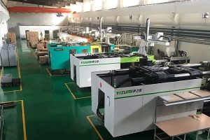
当社の上海工場では、90トンから1850トンまでの47台の射出成形機を稼働しており、8人のシニアエンジニアがDFM(製造性設計)解析中にリブ設計を定期的にレビューしています。私たちが指摘する最も一般的な問題は、リブ形状そのものではなく、リブ先端における十分なベンティング対策の欠如です。ガスを閉じ込めて充填するリブは、ショットごとに焼け跡を発生させ、唯一の修正方法は金型の改造です。設計レビュー段階でこの問題を発見することで、時間とコストの両方を節約できます。月産100セット以上の金型製造能力を持つ自社内金型製造施設により、充填シミュレーションで問題が示された際にリブ形状を迅速に反復修正することが可能です。
Where Are Rib Designs Most Commonly Applied?
リブは主に5つの産業カテゴリーで使用されます:自動車、民生電子機器、電動工具、バッテリーシステム、家電製品です。各用途は、リブ形状、材料選択、外観要件に異なる要求を課します。自動車のドアパネルやバンパーなどの構造部品では、PPやPAを用いたリブで最小重量での剛性目標を達成します。PC/ABS製の民生電子機器筐体では、落下試験性能のためにリブが用いられます。電動工具ケースでは、高剛性ハンドルのためにガラス繊維強化リブが使用されます。バッテリーエンクロージャーでは、熱による反りを抑えるためにリブグリッドが用いられます。家電製品内部では、取り付け部品や構造ブラケットとしてリブが使用されます。リブ設計に万能なアプローチは常に失敗します。なぜなら、各用途には固有の流動、冷却、外観の制約があるからです。
「リブのベースに半径を追加することで応力集中を低減し、材料の流動を助けます。」真
フィレットは切り欠き効果を低減し、衝撃強度を向上させるとともに、溶融プラスチックの流路を滑らかにし、交差点でのせん断応力を低減します。
「リブはノミナルウォールよりも薄いため冷却が速く、特別な冷却対策は必要ありません。」偽
リブ自体は急速に冷却されますが、基部の交差部分は周囲のウォールよりも長く熱を保持します。適切なコア冷却がない場合、このホットスポットはサイクル遅延とシンクマークを引き起こします。
How Should Engineers Optimize Rib Design for Flow and Cooling?
Optimization is a disciplined six-step process covering wall thickness, rib proportions, draft, cooling, simulation, and venting. Our engineering team considers simulation results non-negotiable before committing to production tooling, because the cost of running Moldflow is trivial compared to the cost of modifying a finished mold. The six steps below provide a systematic framework that works across all material types and part geometries.
Step 1 — Establish Nominal Wall Thickness (T): Determine the base wall thickness based on the material flow length ratio and structural requirements. This value anchors every subsequent rib dimension. For most engineering resins, a 2.0 to 3.0 mm nominal wall provides a practical starting point.
Step 2 — Calculate Rib Thickness (t): Apply t = 0.5 x T for high-gloss resins like PC/ABS, or up to t = 0.7 x T for low-shrinkage or textured materials. Never exceed 70% of the nominal wall—doing so virtually guarantees sink marks on the opposite surface. Our recommendation for visible cosmetic surfaces is to stay at or below 50% for maximum safety.
Step 3 — Set Draft and Height: Apply a minimum of 0.5 degrees draft per side. Calculate the resulting thickness at the rib tip—ensure it is not less than 0.75 mm to avoid venting issues and short shots. Limit total rib height to 3x the nominal wall. Taller ribs require disproportionate ejection force and are far more prone to sticking or damage during ejection.
“Flow hesitation occurs when the melt front advances through variable-thickness areas, preferring the path of least resistance.”真
The polymer melt prefers thick sections (low resistance) over thin ribs (high resistance). If the melt slows too much in the rib, it may freeze off before filling completely.
“Increasing injection speed is the only solution to fix short shots in deep ribs.”偽
While speed helps, excessive speed causes jetting, gas burns, and flash. The correct solution involves optimizing rib thickness, gating location, and venting—not simply cranking up the injection velocity.
Step 4 — Plan Cooling at the Intersection: If ribs are deep or clustered, incorporate mold cooling channels (baffles or bubblers) directly into the core steel opposite the ribs. This is not optional for high-production molds—the cost of adding cooling elements during initial build is a fraction of the cost of modifying a production mold to fix cooling problems. The localized cooling at the rib base directly controls cycle time and sink mark severity.
Step 5 — Simulate Flow and Warp: Use Moldflow or equivalent CAE software to check for flow hesitation, weld line placement, and predicted warpage. This step catches problems that no rule-of-thumb can predict, especially in complex parts with multiple rib networks competing for flow. The simulation cost is trivial compared to the cost of a mold modification.
Step 6 — Verify Venting at Rib Tips: Ensure the 金型設計 allows for adequate venting at the end of every rib. Trapped air will superheat under compression pressure (the diesel effect), causing material degradation, burn marks, and even localized carbonization. In practice, this means grinding vent grooves (0.015 to 0.025 mm deep) at rib terminations on the parting line or adding vent pins for blind ribs. This is the single most commonly overlooked detail in rib design—we see it missed in roughly 30% of first-time DFM submissions.
材料選択はリブ性能にどのような役割を果たしますか?
Material selection is the primary driver of rib design parameters because different polymers shrink, flow, and conduct heat at vastly different rates. Amorphous materials like PC and ABS require generous base radii to prevent stress cracking, while semi-crystalline materials like PP and PA have higher shrinkage that demands tighter thickness controls. With experience across 400+ plastic materials, our engineering team selects rib parameters based on the specific resin grade, not generic rules of thumb.
| 素材タイプ | Shrinkage Behavior | Recommended Rib/Wall Ratio | Key Design Consideration |
|---|---|---|---|
| 非晶性 (PC, ABS) | Low, isotropic | 50-60% | Requires generous base radii to prevent stress cracking |
| Semi-crystalline (PP, PA) | High, anisotropic | 40-50% | Higher shrinkage increases sink mark risk; use tighter ratio |
| Glass-filled (PA-GF, PBT-GF) | Lower shrinkage, but anisotropic | 50-65% | Fiber orientation at rib base affects strength and warpage |
| PC/ABS blends | 中程度 | 50-60% | Good balance of flow and rigidity; most forgiving for rib design |
| High-flow grades | Lower viscosity | 45-55% | Better fill in thin ribs but may show more visible sink marks |
“Glass-filled resins allow slightly higher rib-to-wall ratios because their lower shrinkage reduces sink mark severity.”真
The reduced volumetric shrinkage of glass-filled grades means the intersection contracts less during cooling, giving designers more latitude on rib thickness—typically up to 60-65% of the wall.
“All plastic materials respond the same way to rib geometry, so a universal thickness ratio works for every project.”偽
Different polymers have dramatically different shrinkage rates, thermal conductivities, and flow behaviors. A ratio that works perfectly for PP may cause severe sink marks in PC, and vice versa.
よくある質問
よくある質問
Why Do Ribs Cause Sink Marks on the Visible Surface?
Sink marks appear on the cosmetic surface (A-side) opposite a rib because the rib-wall intersection contains significantly more material volume than the surrounding wall. As this concentrated mass cools and shrinks during the molding cycle, it pulls the still-soft outer skin inward, creating a visible depression. Maintaining rib thickness below 60% of the nominal wall and ensuring adequate localized cooling at the intersection are the most effective countermeasures. For critical cosmetic surfaces, we recommend staying at or below 50% to eliminate visible sink entirely. Gas-assist molding and foaming agents can also reduce sink severity in challenging applications.
What Is Flow Hesitation in Ribbed Parts?
Flow hesitation is a filling defect that occurs when the polymer melt front encounters a thin rib entrance and elects to flow through the thicker adjacent wall instead, which presents lower flow resistance. As the melt continues to advance elsewhere, the material at the rib entrance begins to cool and increase in viscosity. If the viscosity rises too high before the rib fills, the material freezes off entirely, resulting in a short shot. Proper rib thickness (within the 40-60% range), strategic gate placement near rib networks, and adequate injection speed all help mitigate this common defect. Moldflow simulation is the most reliable way to predict hesitation before cutting steel.
How Does Material Selection Affect Rib Design Parameters?
Material choice fundamentally changes the rib design equation. Amorphous materials like Polycarbonate (PC) and ABS require generous base radii to prevent stress cracking at the rib-wall junction, and they tend to be more forgiving on sink marks due to lower shrinkage. Semi-crystalline materials like Polypropylene (PP) and Polyamide (PA) have higher volumetric shrinkage during crystallization, making them significantly more susceptible to sink marks and demanding tighter thickness ratios (often below 50%). Glass-filled grades allow slightly higher rib-to-wall ratios because the fiber content reduces overall shrinkage. Always select rib parameters based on the specific resin grade rather than generic guidelines.
Can Ribs Replace Solid Wall Thickness Entirely?
Yes, in many structural applications, replacing a thick solid wall with a thinner wall reinforced by a network of ribs is standard practice. This approach, called coring out, reduces part weight, material consumption, and cycle time while maintaining comparable bending stiffness. The critical constraint is designing the rib network to carry the expected loads without introducing molding defects—each rib must stay within the 40-60% thickness ratio, maintain adequate spacing (at least 2x wall thickness apart), and include proper draft for ejection. Our engineering team routinely evaluates coring-out proposals during DFM review to ensure the structural and manufacturing tradeoffs are balanced correctly.
What Is the Inscribed Circle Method for Rib Design?
The inscribed circle method is a design verification technique where an engineer draws the largest possible circle that fits within the rib-wall intersection cross-section. The diameter of this circle directly represents the local thermal mass—the larger the circle, the more material is concentrated at the junction, and the longer it takes to cool. The goal is to minimize this inscribed circle diameter relative to the nominal wall thickness. A practical target is to keep the inscribed circle diameter no larger than 1.2x the wall thickness, which ensures uniform cooling and minimizes the severity of sink marks on the opposite surface.
How Many Ribs Should You Use Instead of One Thick Rib?
複数の薄いリブを壁厚の少なくとも2倍の間隔で配置することは、ほぼすべてのシナリオにおいて単一の厚いリブよりも優れた性能を発揮します。この分散アプローチにより、構造荷重が複数の小さな接合部に分散され、それぞれがより速く冷却され、一箇所に集中した熱質量よりも深刻なシンクマークが発生しにくくなります。複数のリブはまた、部品全体により均一な剛性をもたらし、非対称収縮による反りの発生リスクも低減します。単一の高さのあるリブが好まれる唯一の状況は、極めてスペースに制約のある設計の場合ですが、その場合でも、製造上のトレードオフ(冷却時間の延長、シンクマークの悪化、高い脱型力)を考慮すると、通常は推奨されません。
推奨リブ高さを超えるとどうなりますか?
公称壁厚の3倍を超える高さのリブは、製造上の問題を連鎖的に引き起こします。リブ先端部の効果的な冷却が困難になり、サイクルタイムの延長や寸法不安定性の原因となります。脱型力はリブ高さに比例して不均衡に増加し、部品取り出し時のリブの引っ掛かり、ひび割れ、変形のリスクが高まります。深いリブはガスが滞留しやすく、ディーゼル効果(圧縮・過熱された空気による焼け跡)を防ぐためには専用のベントピンや多孔質鋼インサートが必要になります。極端な場合、高さ制限を超えるリブは、リフターや横スライドなどの特殊な金型構造を必要とし、金型コストとメンテナンス要件を大幅に増加させます。
20年以上の射出成形経験と上海工場の47台の成形機を有する当社では、8名のシニアエンジニアからなるチームがDFM解析において毎日リブ設計をレビューしています。社内金型製造能力を備えているため、生産用金型の製作着手前に、シミュレーションで流動や冷却の問題が明らかになった場合、リブ形状を迅速に繰り返し改善することが可能です。
リブ設計の専門的なDFMレビューが必要ですか?当社のエンジニアリングチームが、金型投入前に部品形状、材料選択、成形性に関する詳細なフィードバックを提供します。競争力のある価格設定、シミュレーションに基づく工程最適化、生産タイムラインをZetarMoldからご提供します。無料見積もりをリクエストしてください。




 EN
EN  ES
ES  FR
FR  DE
DE  PT
PT  AR
AR  RU
RU  JA
JA  KO
KO  IT
IT  NL
NL  TR
TR  PL
PL 