 Skip to content

Introduction: The parting line is the line where the mold opens to remove the product. Choosing the parting line is also the first step in mold design. It is affected by many factors such as the shape, appearance, wall thickness, dimensional accuracy, and number of mold cavities of the product.
For general products, I believe that everyone has no problem with the determination of the parting line. But for many side core pulling, or when it involves pillow position, collision, and insertion.

These are controversial. How to choose is sometimes not a simple matter. Therefore, Zetar Mold will talk about how to choose the parting line and how to determine the parting line.
The Meaning of the Parting Surface
The so-called parting is to divide the mold core of the molding part of the plastic part into several modules. The contact surface between the modules is called the parting surface, also called the parting surface.parting line injectionmolding refers to the visible lines on the mold parting surface formed during the injection molding process .
In injection molded, the parting line location determines the separation of the mold and the appearance of the molded part .The parting line is located on the edge of the molded part, between the core and the cavity surface. The parting line includes vertical parting line, mold parting line, straight parting line, etc.

In injection molding design, the parting line determines the opening and closing position of the mold halves.The position of the parting line is closely related to the fit of the core and cavity, and directly affects the appearance of the molded part. During the injection molding process, the parting line will form a witness line on the surface of the finished product, reflecting the accuracy of the mold design.
Types of Parting Surfaces
Plane Parting Surfaces
Parting surfaces on a mold are pretty common and simple. They are just planes that are perpendicular to the direction the mold opens.

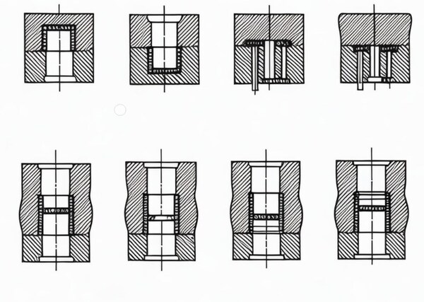
Stepped Parting Surfaces
Based on the specific requirements of some plastic parts, the parting surfaces are designed to be stepped. For the stepped parting lines, because there is a large force on one side of the cavity, injection eccentric forces are generated on both sides of the cavity, resulting in a relative sliding tendency between the fixed half mold and the movable half mold.
The sliding direction is shown in the figure below. Therefore, the parting surface with a shallow step surface (the side with a larger vertical projection area) should be selected first.

When you set up the mold, make sure to set up the two cavities symmetrically. Balance the injection pressure on both sides of the mold body and make the mold structure compact.If the step difference of the stepped parting surface is too large, consider designing a pillow position and making a stepped parting surface locally.
Some parts have a lot of steps. If the parting surface is designed according to the stepped shape, the parting surface becomes complicated.In order to simplify the parting surface, the parting surface can be made into a plane. The disadvantage is that there will be a clamping line on the appearance of the part. Therefore, this parting method is mostly used for internal parts.
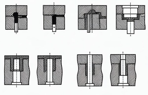
Chamfered Parting Surface
The parting surface of the molding part is beveled, and a sealing surface is created along the bevel (to save mold), and then flattened (to make it easier to process positioning and data collection).
Basic Principles for Selecting Parting Surfaces
Determining the parting surface is a complex matter. The parting surface is influenced by the molding position of the plastic part in the injection mold, the design of the pouring system, the structural processability and precision of the plastic part, the position and shape of the insert, as well as the ejection method, injection molding The mold manufacturing, exhaust, operation process and other factors affect the selection of the parting surface.
Therefore, when selecting the parting surface, a comprehensive analysis and comparison should be made. Generally, the following basic principles should be followed when selecting the parting surface:

It Should Meet the Demoulding Requirements
Typically, you want the plastic part to stay on the moving side of the mold when it opens as much as possible. This helps the ejector mechanism in the moving side of the mold to work. Otherwise, if the part stays on the fixed side of the mold after it shrinks, you have to put an ejector mechanism in the fixed side of the mold, which makes the mold more complicated.
After the mold opens, the part remains on the moving half of the mold, and the plastic part can be ejected by the ejection system of the injection machine and the ejection mechanism of the injection mold.
Sometimes, even if you choose a parting line that keeps the plastic parts on the side of the moving mold, different positions will still affect the complexity of the injection mold structure and the difficulty of stacking the plastic parts.Even if the plastic parts stay on the moving mold after the parting line, it is difficult to set up an effective ejection mechanism when the hole spacing is small.
Even if you can set it up, the required ejection force is large, which will increase the complexity of the injection mold structure and easily cause bad consequences, such as warping and opening of the plastic parts.It is more reasonable to only set a simple ejection plate on the moving mold as an ejection mechanism.
Simplified Mold Structure Should be Considered
If the structural accuracy requirements for the side features aren’t high, try to avoid using the side core pulling (slider) mechanism, simplify the mold structure, reduce the mold size, and reduce the mold cost to some extent.If you can’t avoid using a side core-pulling (slider) mechanism, choose a parting line that allows the shortest possible side core-pull distance and reduces the size of the mold.

Also, make sure the large core is in the direction of mold opening because the clamping force is large. If it’s on the side of the mold with the side mechanism, it’s not easy to demold.
Ensure the Precision Requirements of Plastic Parts
If the height dimension in the direction perpendicular to the parting surface has high precision requirements, or the shape or inner hole has high coaxiality requirements, it should be placed in the same half mold cavity as much as possible to ensure its precision.

If the mold surface that requires high precision for the plastic part is divided by the parting surface, it may cause shape and size deviations that cannot be allowed due to the influence of the mold clamping force, and the plastic part may be scrapped because it cannot meet the required precision requirements.
Meet the Appearance Quality Requirements of Plastic Parts
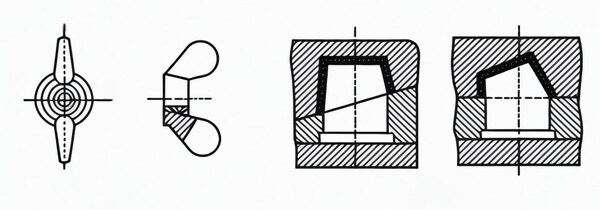
When choosing the parting line, it should avoid affecting the appearance quality of the plastic part. At the same time, it is necessary to consider whether the flash generated at the parting line is easy to trim.
If possible, avoid flash at the parting line. Flash at the rounded corner is difficult and will affect the appearance of the plastic part: Flash at the rounded corner is easy and will not affect the appearance of the plastic part.
Easy to Process and Manufacture Injection Molds
To make it easier to process and manufacture injection molds, try to choose a straight parting surface or a parting surface that is easy to process. If you use a straight parting surface, the shape of the lower end of the plastic part is made on the push rod.
This push rod is difficult to process, and anti-rotation measures must be taken during assembly. At the same time, it will be damaged by the lateral force.If you use a stepped parting surface, it is easy to process, but the core and mold amine are difficult to process. If you use an inclined parting surface, it is easier to process.
Reduce the Projection Area of the Plastic Part on the Mold Parting Surface
When designing the parting surface of an injection mold, the injection machine usually specifies the molding area and the rated clamping force allowed for the corresponding injection mold.During the injection molding process, if the projected area of the plastic part on the parting surface of the mold exceeds the allowed molding area, the mold will expand and overflow.

At this time, the clamping force required for injection molding will also exceed the rated clamping force. Therefore, in order to reliably clamp the mold and avoid mold expansion and overflow, the projected area of the plastic part on the parting surface should be minimized when selecting the parting surface.
If the projected area of the plastic part on the parting surface of the mold is large, the clamping reliability of the mold is poor; if the parting surface is used, the projected area of the plastic part on the parting surface of the mold is small, which ensures the clamping reliability of the mold.
It is Conducive to Improving the Exhaust Effect
The parting surface should be as close as possible to the inner wall surface of the cavity where the end of the plastic melt flow is located when the cavity is filled. The exhaust effect is poor: the structure is beneficial to the exhaust during the injection process, so the parting is reasonable.

Make the Cavity Depth the Shallowest.
The depth of the mold cavity size has three effects on the mold structure and manufacturing:Right now, the way we make the mold cavity is mostly by EDM. The deeper the cavity, the longer it takes to make, which slows down the mold making process and costs more money.The depth of the mold cavity affects the thickness of the mold. The deeper the cavity, the thicker the movable and fixed molds.
On the one hand, the processing is more difficult; on the other hand, various injection machines have certain restrictions on the maximum thickness of the mold, so the cavity depth should not be too large.The deeper the cavity, the more the actual size difference between the upper and lower ends of the same size at the same draft.

If the specified dimensional tolerance is to be controlled, the draft must be reduced, which will make it difficult to eject the plastic part. Therefore, when selecting the parting surface, the cavity should be as shallow as possible.
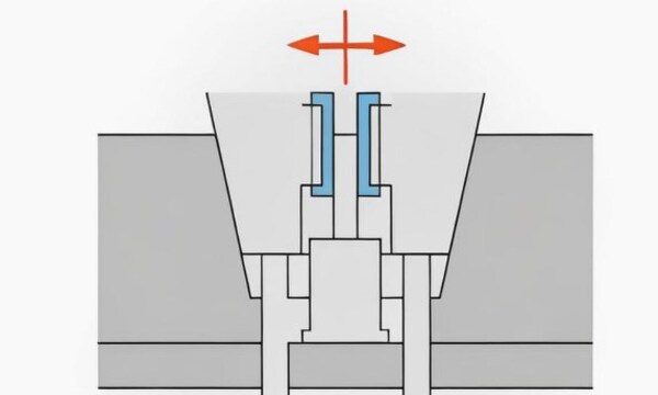
Set the Lateral Core Pulling Mechanism on the Side of the Movable Mold
When designing the parting surface of the injection mold, if the plastic part needs to be pulled from the side, in order to ensure the easy placement of the lateral core and the smooth operation of the core pulling mechanism, when selecting the parting surface, the shallowest parting surface should be selected.

Then use the hole or short lateral convex as the core pulling direction. Place the deeper hole or higher convex in the direction of opening and closing the mold. Try to set the lateral core pulling mechanism on the side of the movable mold.
Methods for Determining the Parting Surface
Simulation Assembly Method
The method of simulating assembly is to simulate the assembly according to the module structure and the plastic part structure to determine the parting surface of the mold. The specific steps are as follows:First put the module structure and the plastic part structure, and lock them to get the overall structure of the mold.
Divide the components in the structure of the plastic part according to the requirements of the parting surface (such as the molding sequence and the direction of demolding), and mark the corresponding parts in the module structure.

By extruding, rotating, and tilting each component, the position and direction of the parting surface are determined, and the mold parting surface is finally obtained.
Copy Method
The copy method is to copy each component of the plastic part structure with an acrylic plate, and then arrange them in a certain pattern according to the molding sequence to obtain the entire mold structure, and then determine the mold parting surface by comparison. The specific steps are as follows:

Copy each component of the plastic part structure with an acrylic plate, arrange them in a molding sequence, and mark the sequence and direction on each component.Arrange the copies in a certain pattern to simulate the assembly into a mold structure. Determine the position and direction of the parting surface by comparison.
Schematic Diagram Method
The way to use the schematic diagram method is to match the cross-sectional view of the plastic part with the plane view of the mold to determine the parting surface. The specific steps are as follows:

Make a drawing that shows what the plastic part looks like when you cut it in half. Label the different parts and show how they were made.Look at the top view of the mold and find the view that matches the drawing.On that view, draw the shape and location of the mold parts and decide where the mold will be split.
Computer-Aided Design
CAD is to separate each part through computer simulation based on virtual molding operation, and then determine the parting surface. The specific steps are as follows:Use the computer to draw the structure of the plastic part and the module structure, simulate the assembly, and separate the parts according to the molding order.
By computer simulation of the extrusion, rotation and tilting of each part, determine the position and direction of the parting surface, and finally obtain the mold parting surface.

Summary
Deciding where to split the mold is a big deal. It affects how the mold works, how much it costs, and how good the parts are. The parting surface can be divided into planes, stepped surfaces, inclined surfaces and Curved surface.
When you pick the split line, you have to think about what the part looks like, how it comes out of the mold, how hard the mold is to make, and how easy it is to machine. If you pick the right split line, you can make the mold better, make parts faster, and make better parts.


