 Skip to content

– Warpage occurs when differential shrinkage creates internal stresses that bend or twist a molded part after ejection.
– The top causes include uneven cooling, inconsistent wall thickness, improper gate location, and poor material selection.
– In our factory, optimizing cooling channel layout alone has reduced warpage by up to 40% on flat panel geometries.
– Combining mold flow simulation with empirical tuning is the most reliable way to eliminate warpage in production.
What Is Injection Molding Warpage and Why Does It Happen?
Injection molding warpage is the unintended distortion of a plastic part after it is ejected from the mold. Instead of maintaining the designed geometry, the part bows, twists, or curves due to uneven internal stresses. In our experience at ZetarMold, warpage is one of the top three quality complaints we see from new mold transfers — and it is almost always preventable.
At its core, warpage results from differential shrinkage1. When one region of the part shrinks more than another during cooling, internal stresses build up. Once the part is released from the mold’s constraining cavity, those stresses relieve themselves by bending the part. The difference can be as small as 0.1–0.3% in local shrinkage rates, yet the resulting distortion may be several millimeters — enough to fail dimensional inspection or prevent assembly.
What Are the Primary Causes of Warpage in Injection Molding?
Warpage has multiple root causes that often act together. Understanding each one is the first step toward a systematic fix. Below is a breakdown of the most common factors we encounter on the factory floor.
| Cause Category | Mechanism | Typical Impact |
|---|---|---|
| Uneven cooling | Hot spots create differential shrinkage | Bowing toward hotter side, 0.5–3 mm distortion |
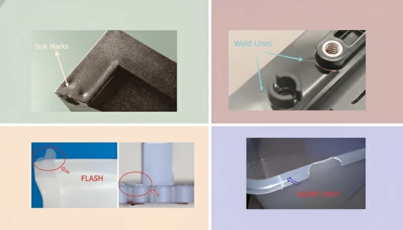
| Non-uniform wall thickness | Thick sections shrink more than thin sections | Sink marks + warpage near ribs and bosses |
| Improper gate location | Unbalanced flow creates orientation stress | Twist warpage, especially in long flat parts |
| Excessive packing pressure | Over-packing one zone vs. another | Stress-induced bending after ejection |
| Material choice | Semi-crystalline polymers have higher, less uniform shrinkage | 1.5–3% shrinkage in PP/PA vs. 0.4–0.7% in ABS/PC |
| Premature ejection | Part not rigid enough when ejected | Mechanical deformation by ejector pins |
“Warpage is mainly caused by using the wrong plastic material.”False
While material choice affects shrinkage rate, warpage is most often caused by non-uniform cooling and inconsistent wall thickness in the part design. A well-designed mold can produce warp-free parts even with high-shrinkage materials like polypropylene.
“Uneven cooling is the single biggest contributor to warpage in most injection molding applications.”True
Studies and our factory data consistently show that temperature differentials across the mold cavity — often just 5–10°C — are responsible for the majority of warpage cases. Balancing cooling circuits is the highest-impact countermeasure.
How Does Mold Design Influence Warpage?
Mold design is the single most powerful lever for preventing warpage. A well-engineered mold distributes heat evenly, fills the cavity in a balanced pattern, and ejects the part without introducing mechanical stress. In our tooling shop, we run mold flow analysis2 on every new project before cutting steel — and it catches potential warpage issues about 80% of the time.
Key mold design factors include:
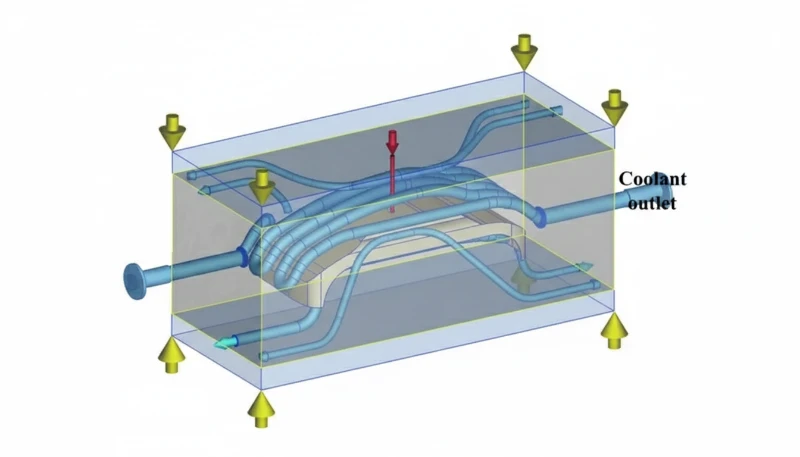
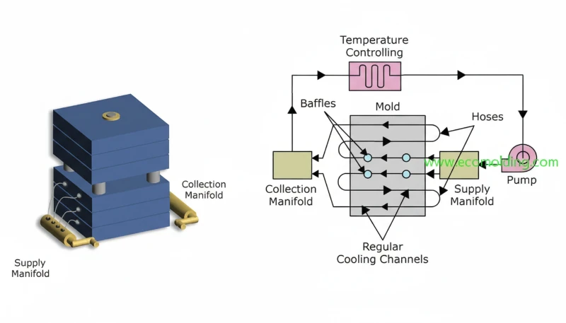
- Cooling channel layout — Channels should follow the part contour at consistent distance. We target 8–12 mm from the cavity surface with 2–3D spacing between channels (where D is channel diameter).
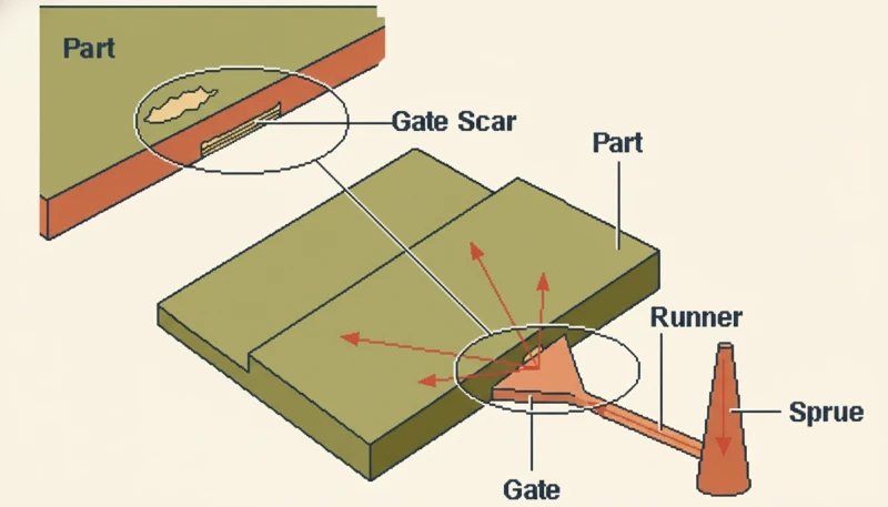
- Gate type and location — Central gates minimize flow-length differences. For long flat parts, multiple gates or a fan gate prevent orientation-driven warpage.
- Ejection system — Ejector pins placed at stiff ribs or thick sections prevent push-through deformation. We use sleeve ejectors for cylindrical features.
- Venting — Trapped air creates hot spots that slow local cooling, contributing to differential shrinkage.
What Role Does Material Selection Play in Controlling Warpage?
Material selection sets the baseline shrinkage behavior that the mold and process must accommodate. Semi-crystalline polymers like polypropylene (PP) and nylon (PA) shrink 1.5–3.0%, while amorphous materials like ABS and polycarbonate (PC) shrink only 0.4–0.8%. More importantly, semi-crystalline materials exhibit direction-dependent shrinkage — they shrink more perpendicular to flow than along it.
| Material | Shrinkage Range (%) | Warpage Risk | Notes |
|---|---|---|---|
| ABS | 0.4–0.7 | Low | Isotropic shrinkage, excellent dimensional stability |
| PC | 0.5–0.7 | Low | Low shrinkage but sensitive to residual stress |
| PP (unfilled) | 1.5–2.5 | High | Strong crystallinity-driven differential shrinkage |
| PA6 (unfilled) | 1.0–2.5 | High | Moisture absorption can cause post-mold dimensional change |
| PP + 20% GF | 0.3–1.0 | Medium | Glass fiber reduces shrinkage but increases anisotropy |
| POM | 1.8–2.5 | High | Very uniform crystalline structure, but high overall shrinkage |
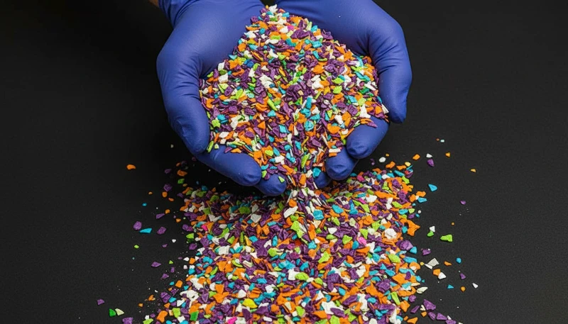
In our factory, when a customer insists on PP for cost reasons but the part is a large flat panel, we typically recommend PP + 20% talc filler. The talc reduces shrinkage to 0.8–1.2% and significantly improves isotropy, cutting warpage risk by roughly half.
How Can You Optimize Process Parameters to Minimize Warpage?
Process optimization is the fastest and cheapest way to reduce warpage on an existing mold. It does not require new tooling — just systematic adjustment of machine settings based on data.
The most effective parameters to tune are:
- Mold temperature — Raise both halves to equalize temperature. For PP, we run 40–60°C; for PC, 80–100°C. A 10°C differential between core and cavity sides is a common warpage trigger.
- Packing pressure and time — Reduce holding pressure3 gradually until gate freeze-off. Over-packing one area while another is frozen causes stress imbalance.
- Cooling time — Extend cooling until the part center drops below the heat deflection temperature (HDT). We use infrared thermography to verify surface temperature at ejection.
- Injection speed — A moderate, profiled injection speed reduces molecular orientation differences across the part.
“Increasing packing pressure always reduces warpage by forcing the part to fill more uniformly.”False
Excessive packing pressure can actually worsen warpage by over-packing areas near the gate while distant regions remain under-packed. The resulting pressure gradient creates differential shrinkage and internal stress that bends the part after ejection.
“Equalizing mold temperature between core and cavity sides is one of the most effective process-level warpage countermeasures.”True
When core and cavity temperatures differ by more than 5–10°C, the part shrinks asymmetrically through its thickness, causing it to bow toward the hotter side. Balancing mold temperatures is a quick, high-impact adjustment that costs nothing.
What Are Practical Solutions for Fixing Warpage on Existing Parts?
When warpage appears in production, we follow a structured troubleshooting protocol at ZetarMold. The approach moves from least-cost to highest-cost interventions.
Step 1: Process adjustment (0 cost, 1–2 hours)
- Equalize core/cavity mold temperatures
- Reduce packing pressure by 5–10% increments
- Extend cooling time by 2–5 seconds
- Lower melt temperature by 5–10°C
Step 2: Cooling system improvement (low cost, 1–3 days)
- Add baffles or bubblers to hot-spot areas
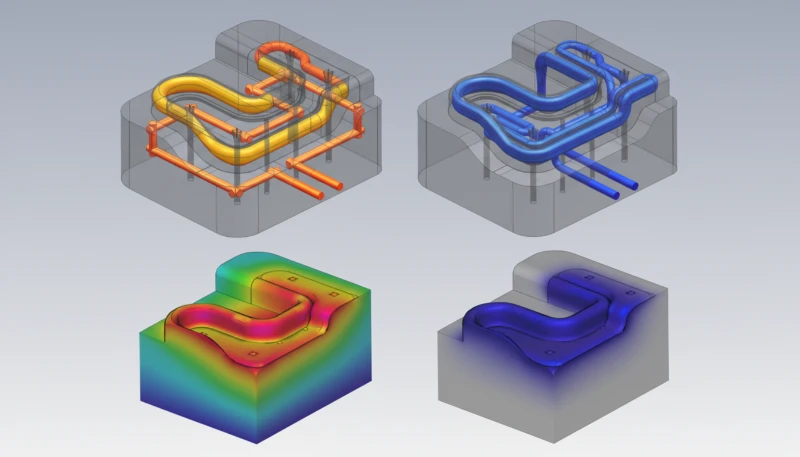
- Switch to conformal cooling4 inserts for complex geometries
- Verify coolant flow rate and temperature at each circuit
Step 3: Mold modification (medium cost, 1–2 weeks)
- Add or relocate gates for better flow balance
- Modify wall thickness by steel-safe changes (adding steel to reduce thickness)
- Add ribs or structural features to stiffen the part
Step 4: Post-mold fixturing (workaround)
- Use cooling jigs or fixtures that constrain the part shape while it finishes cooling
- This does not eliminate internal stress but controls the final geometry
How Does Wall Thickness Design Affect Warpage?
Non-uniform wall thickness is the most common design-related cause of warpage. Thick sections take longer to cool and shrink more than thin sections, pulling the part inward. The golden rule in injection molding design is to maintain wall thickness as uniform as possible — ideally within ±10% variation.
Practical design guidelines we follow:
- Rib thickness: 50–60% of the adjacent wall thickness. Thicker ribs create sink marks and local warpage.
- Boss design: Wall thickness of the boss should equal 60% of the nominal wall.
- Transitions: Use gradual tapers (3:1 ratio minimum) when thickness changes are unavoidable.
- Core-out thick sections: Replace solid thick areas with hollow ribbed structures to equalize cooling.
What Real-World Results Can You Expect from Warpage Optimization?
At ZetarMold, we track warpage data across projects. Here are representative results from recent optimization work.
| Project | Material | Before (mm) | After (mm) | Method |
|---|---|---|---|---|
| Automotive center console panel | PP + 20% talc | 2.8 | 0.6 | Conformal cooling + gate relocation |
| Electronic housing cover | ABS | 1.2 | 0.3 | Process optimization only |
| HVAC duct panel | PP | 3.5 | 0.9 | Wall thickness redesign + cooling jig |
| Medical device enclosure | PC | 0.8 | 0.2 | Mold temperature balancing |
These results demonstrate that warpage can typically be reduced by 60–80% through a combination of design, mold, and process improvements. The key is systematic root-cause analysis rather than trial-and-error.
Ready to solve warpage issues in your injection molding project? Contact ZetarMold for a free DFM review and warpage risk assessment.
FAQ
What is the acceptable warpage tolerance for injection molded parts?
Acceptable warpage depends on the application. For general consumer products, 0.5–1.0 mm over 200 mm length is typical. For precision assemblies like automotive or electronics, tolerances tighten to 0.1–0.3 mm. At ZetarMold, we discuss flatness requirements during the DFM stage to set realistic targets.
Can warpage be completely eliminated?
In theory, zero warpage is impossible because all plastics shrink during cooling. In practice, warpage can be reduced below measurable thresholds for most applications. The goal is to keep distortion within the part’s functional tolerance, not to achieve absolute zero.
Does glass fiber filler always reduce warpage?
Glass fiber reduces overall shrinkage but introduces anisotropic shrinkage — the part shrinks differently along and across the fiber orientation. This can create a different type of warpage. Short fiber (chopped GF) in a well-designed part generally helps; long fiber can make warpage worse if flow patterns are not controlled.
How does mold temperature affect warpage direction?
The part tends to bow toward the hotter mold surface. If the core side is 20°C hotter than the cavity side, the part curves inward (toward the core). This principle is sometimes used intentionally to counteract design-driven warpage.
What is the fastest way to diagnose warpage root cause?
Run a short-shot study combined with infrared thermal imaging at ejection. The short shots reveal fill balance, while the thermal images show cooling uniformity. Together, they pinpoint whether warpage is flow-driven, cooling-driven, or both within one hour of testing.
Is warpage worse in hot runner molds or cold runner molds?
Neither system is inherently worse. Hot runner systems can create more uniform fill but may introduce temperature variation at the gate tips. Cold runner systems waste material but sometimes offer more even packing. The key factor is balanced fill and cooling, regardless of runner type.
Summary
Injection molding warpage is a solvable problem when approached systematically. The root cause is always differential shrinkage — whether driven by uneven cooling, non-uniform wall thickness, poor gate placement, or material properties. At ZetarMold, our approach combines mold flow simulation during design, precision cooling system engineering, and data-driven process optimization to deliver parts that meet tight flatness tolerances consistently. If you are struggling with warpage on an existing mold or designing a new part with challenging geometry, our engineering team can help you find the most cost-effective solution.
-
Differential shrinkage is the variation in volumetric contraction between different regions of a molded part during cooling, caused by differences in temperature, pressure, crystallinity, or molecular orientation across the part geometry. ↩
-
Mold flow analysis is a computer simulation technique that predicts how molten plastic fills a mold cavity, where weld lines form, how the part cools, and how much it will shrink and warp — enabling engineers to optimize the mold design before manufacturing. ↩
-
Holding pressure (also called packing pressure) is the pressure maintained on the molten plastic after the cavity is filled, compensating for volumetric shrinkage as the material cools and solidifies inside the mold. ↩
-
Conformal cooling uses cooling channels that follow the contour of the part geometry — typically produced by 3D metal printing — to achieve more uniform heat extraction than conventional straight-drilled cooling lines. ↩


