 Skip to content

Wall thickness[1] is arguably the single most important design parameter in injection molding. Get it right, and your part molds cleanly, functions reliably, and costs less. Get it wrong, and you’re dealing with sink marks, warpage, voids, and cycle times that eat your margin.
Key Takeaways:
- Keep nominal wall thickness between 1.5–3.0 mm for most engineering thermoplastics.
- Maintain wall variation within ±25% of the nominal value throughout the part.
- Use 3:1 taper ratio for transitions between different wall thicknesses.
- Keep rib base thickness at 50–60% of nominal wall to avoid sink marks.
- Cooling time scales with the square of wall thickness — thin-wall design has high ROI.
This guide covers everything engineers need to know about injection molding wall thickness: how to choose the right value, what happens when walls aren’t uniform, material-specific guidelines, and the most common mistakes from thousands of DFM reviews.
What Is Wall Thickness in Injection Molding?
Wall thickness is the distance between the outer and inner surface of a molded part at any cross-section. It determines how plastic flows through the injection mold cavity, how quickly the part cools, and whether final dimensions hold to specification.
“Wall thickness variation should stay within ±25% of the nominal value.”True
The industry guideline is ±25% variation. Exceeding this without gradual transitions causes differential shrinkage, warpage, and dimensional instability.
“A rib with base thickness equal to 80% of the nominal wall will not cause sink marks.”False
Ribs thicker than 50–60% of nominal wall almost always produce visible sink marks because the rib creates a localized hot spot that cools much slower than the surrounding wall.
Thinner walls save material and reduce cycle time, but increase injection pressure requirements and risk short shots. Thicker walls flow more easily but cool slowly, extending cycle time and increasing the risk of voids and sink marks. The sweet spot for most engineering thermoplastics is 1.5–3.0 mm. Always verify your chosen thickness against the material supplier’s data sheet and flow simulation results before finalizing the design.
Why Is Uniform Wall Thickness So Important?
Non-uniform wall thickness is the root cause of more molding defects than any other single design error. When walls vary significantly, thick sections cool and shrink at a different rate than thin sections. This differential shrinkageinjection molding[2] creates internal stresses that manifest as warpage, sink marks, and dimensional instability.
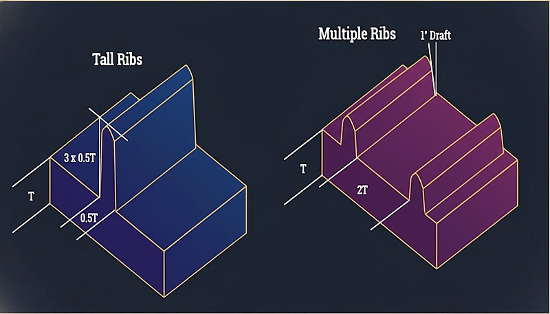
“Multiple thin ribs are generally better than one tall, thick rib for stiffness.”True
Multiple thin ribs distribute stress evenly, cool faster, and produce minimal sink marks compared to a single thick rib creating a localized thermal mass.
“A sharp 90° transition from 3 mm to 1.5 mm wall is acceptable if the thinner section is short.”False
Abrupt transitions create stress concentrations regardless of length. They cause flow hesitation, increased residual stress, and visible surface defects. Always use the 3:1 taper ratio.
The guideline is straightforward: maintain wall thickness within ±25% of the nominal value throughout the entire part. If your nominal wall is 2.5 mm, every section should fall between 1.9 mm and 3.1 mm.
What Is the Recommended Wall Thickness by Material?
Different materials have different flow characteristics and shrinkage rates. Here’s a practical reference table based on extensive production data.
| Material | Min Wall (mm) | Ideal Range (mm) | Max Practical (mm) |
|---|---|---|---|
| ABS | 0.8 | 1.5–3.0 | 4.5 |
| PC (Polycarbonate) | 0.8 | 1.5–3.0 | 4.5 |
| PP (Polypropylene) | 0.6 | 1.2–2.5 | 5.0 |
| PA (Nylon 6/66) | 0.6 | 1.0–3.0 | 4.0 |
| POM (Acetal) | 0.8 | 1.0–3.0 | 4.0 |
| PMMA (Acrylic) | 0.8 | 1.5–3.5 | 5.0 |
| PBT | 0.8 | 1.0–3.0 | 4.0 |
| PE (Polyethylene) | 0.6 | 1.0–2.5 | 5.0 |
| PS (Polystyrene) | 0.8 | 1.0–3.0 | 4.5 |
| TPE/TPU | 0.5 | 1.0–3.0 | 5.0 |
The minimum wall values represent what’s technically possible with optimized processing, not what’s recommended for production. For reliable manufacturing, stay within the ideal range.
How Do You Transition Between Different Wall Thicknesses?
Sometimes wall thickness variation is unavoidable. When it happens, the transition between thick and thin sections is critical. The standard guideline is a 3:1 taper ratio: for every 1 mm of thickness change, provide at least 3 mm of gradual transition.
Abrupt thickness changes cause flow hesitation, stress concentrations, and visible sink marks on the opposite surface. In severe cases, parts crack at thickness transitions during assembly because residual stress exceeds the material’s yield strength.
What Happens When Walls Are Too Thick?
Thick walls create three problems: excessive cycle time, internal voids, and sink marks.
Cycle Time Penalty
Cooling time scales approximately with the square of wall thickness. A part with 2 mm walls might cool in 15 seconds; the same geometry with 4 mm walls could take 50–60 seconds. Across a production run of 100,000 parts, that’s thousands of additional machine hours.
“Cooling time scales with the square of wall thickness — doubling wall quadruples cooling time.”True
This non-linear relationship is why thin-wall design has such high ROI. Reducing wall from 4mm to 2mm can cut cooling time by 75%.
“Reducing wall thickness always improves part quality and production efficiency.”False
While thin walls reduce material usage and cycle time, walls that are too thin cause short shots, increase injection pressure requirements, and compromise structural integrity. The optimal thickness balances flow, strength, and cost.
Internal Voids
When thick sections cool, the outer skin solidifies first while the interior is still molten. As the interior shrinks, it pulls away from the solidified skin, creating internal voids that reduce structural integrity — particularly problematic in load-bearing applications.
Sink Marks
Sink marks are the surface manifestation of the same phenomenon. When material at a thick section shrinks, it pulls the surface inward, creating a visible depression especially noticeable on glossy surfaces. Rib-to-wall ratios directly control sink severity: ribs thicker than 50–60% of nominal wall almost always produce visible sink marks.
What Happens When Walls Are Too Thin?
Thin walls carry their own risks. The most immediate is short shots — the plastic melt freezes before completely filling the cavity. This is especially problematic with high-viscosity materials like polycarbonate and long flow paths, where the melt viscosity is already high.
Thin walls also increase injection pressure requirements. If required pressure exceeds machine capability, you get incomplete fills and high residual stress.
Structural integrity is another concern — always include a safety margin for thin-wall parts in consumer products subject to drop testing. A part that survives static loads may crack on impact if walls are too thin.
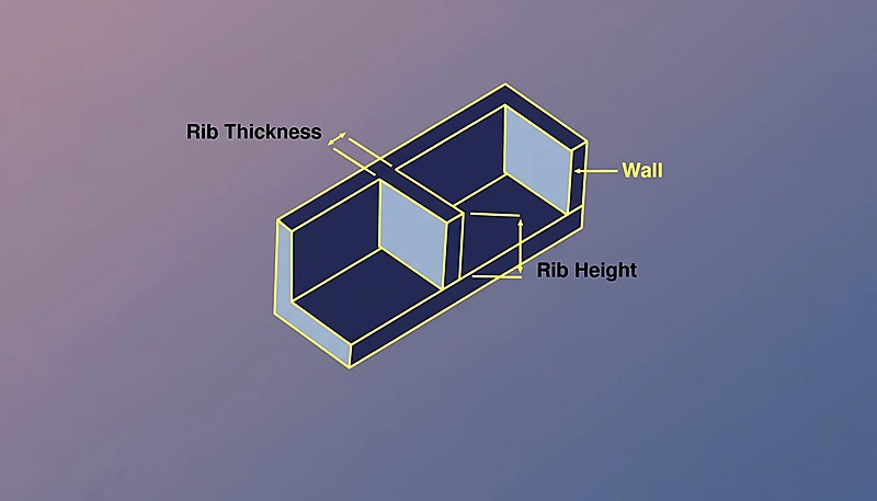
How Do Ribs and Bosses Affect Wall Thickness?
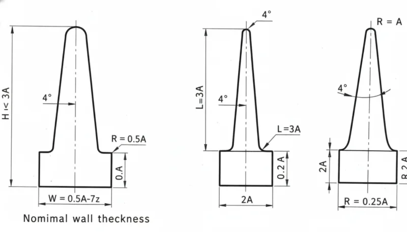
Ribs and bosses are the most common features that interact with wall thickness. For ribs: base thickness should be 50–60% of nominal wall, height should not exceed 3× nominal wall, and multiple thin ribs are better than one tall, thick rib.
For bosses, coring is the solution — hollow out the center with a core pin to maintain uniform wall thickness. Boss outside diameter should be no more than 2–3 times the hole diameter. Parts that follow these proportinjection moldingional injection mold[3] mold cleanly; those that deviate generate ongoing quality issues.
How Does Wall Thickness Affect Cycle Time?
In injection molding, cooling time[4] typically represents 50–70% of total cycle time, governed by the thickest cross-section.
| Nominal Wall | Typical Cooling Time | Relative Cycle Cost |
|---|---|---|
| 1.5 mm | 8–12 seconds | 1.0× (baseline) |
| 2.0 mm | 12–18 seconds | 1.3× |
| 2.5 mm | 18–25 seconds | 1.6× |
| 3.0 mm | 25–35 seconds | 2.0× |
| 4.0 mm | 40–60 seconds | 3.0× |
Going from 2.0 mm to 3.0 mm walls roughly doubles per-part manufacturing cost through cycle time alone. Thin-wall design, when structurally feasible, is one of the highest-ROI optimizations in injection molding.
What Are the Most Common Wall Thickness Mistakes?
- Neglecting uniform thickness. Parts designed without thickness analysis have areas 3× thicker than nominal alongside sections at half nominal wall, causing sink marks, warpage, and extended cycle times.
- Over-thickening for strength. Engineers add material when a rib would be lighter, faster to produce, and more dimensionally stable.
- Ignoring rib proportions. Ribs at 80–100% of nominal wall cause deep sink marks. The 50–60% rule applies to every material.
- Abrupt thickness transitions. Sharp changes without taper create stress risers and cosmetic defects.
- Not running flow simulation. Modern tools predict fill patterns, pressure, and cooling with high accuracy. Skipping simulation on complex parts usually loses.
What Should You Check Before Submitting Your Design?
Before submitting your design for tooling, run through this checklist. Each item takes seconds to verify and can prevent costly tooling revisions.
| Check Item | Pass Criteria |
|---|---|
| Nominal wall within material ideal range | ✓ |
| Wall variation within ±25% of nominal | ✓ or noted |
| All ribs ≤60% of nominal wall | ✓ |
| Thickness transitions use 3:1 taper | ✓ |
| Boss OD ≤3× hole diameter | ✓ |
| Thickest section identified and reviewed | ✓ |
| Flow simulation completed | ✓ |
Optimizing wall thickness before the mold is built is essential — the cheapest place to fix a thickness problem is in CAD, not in steel.
Frequently Asked Questions About Wall Thickness
What Is the Minimum Wall Thickness for Injection Molding?
For most engineering thermoplastics (ABS, PC, Nylon), 0.8 mm is the practical minimum for short flow paths. For high-flow materials like PP and PE, you can go as thin as 0.5 mm. These minimums require high injection pressure and carry risk of short shots.
Can Wall Thickness Vary Across a Part?
Yes, but variation should stay within ±25% of the nominal wall, with gradual transitions using a 3:1 taper ratio between different thicknesses.
How Is Wall Thickness Related to Shrinkage?
Thicker sections shrink more because more material is cooling and contracting. This differential shrinkage is the primary cause of warpage in injection molded parts.
Does Wall Thickness Affect Part Strength?
Yes, but not linearly. Doubling wall thickness more than doubles bending stiffness (it scales with thickness cubed). However, thickening walls also increases residual stress and void risk. Properly proportioned ribs often achieve better strength-to-weight performance.
How Do You Measure Wall Thickness?
Use thickness analysis tools in your CAD software (SolidWorks, Creo, and most MCAD packages have them built in). On physical parts, ultrasonic thickness gauges provide non-destructive measurement, or cut cross-sections for direct measurement with calipers. During production, ultrasonic gauging is the standard method for ongoing quality monitoring.
What Is Thin-Wall Molding?
Thin-wall molding refers to parts with wall thickness below 1.0 mm (sometimes as thin as 0.3 mm for electronics housings). It requires high-speed machines capable of very high pressures (200+ MPa) and specialized mold design.
Bottom line: Keep wall thickness between 1.5–3.0 mm, maintain ±25% uniformity, use 3:1 taper transitions, and keep ribs at 50–60% of nominal wall. These four rules prevent 90% of wall-thickness-related defects.
Wall thickness decisions made early in design determine whether your part molds efficiently or fights you throughout production. If you want a DFM review from engineers who’ve optimized thousands of wall thickness designs across 400+ materials, reach out to our team at ZetarMold. We operate 45 injection molding machines (90T–1850T) from our Shanghai facility, with 30+ English-speaking project managers ready to help.
-
Wall thickness design — BASF, “Part and Mold Design,” Plastics Technology Handbook, 2023. ↩
-
Differential shrinkage — Autodesk, “Moldflow Design Guide,” 2024. ↩
-
Design guidelines — “Wall Thickness Best Practices,” Society of Plastics Engineers, 2025. ↩
-
Cooling time — “Injection Molding Cooling Optimization,” Plastics Technology, 2024. ↩


