 Skip to content

- 80% of defects trace back to process, design, material, or mold issues
- Sink marks and warpage account for 60% of visual rejects
- DFM review prevents 70–80% of potential defect sources
- Flash signals excessive pressure or worn tooling
- Always identify root cause before adjusting parameters
See our injection molding guide and injection mold design guide for broader process context.
What Are the Most Common Injection Molding Defects?
The most common defects include sink marks, Flash1, warpage, voids, short shots, burn marks, silver streaks, jetting, and weld lines. Each has a distinct visual signature and root cause. Our 45 machines running 400+ materials across hundreds of thousands of cycles show sink marks and warpage lead at 60% of visual rejects, with flash at 20%.
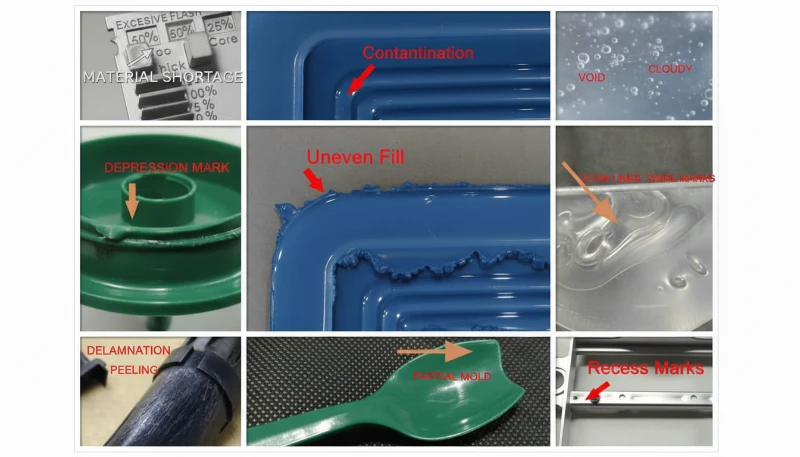
Sink marks appear as shallow depressions over ribs or thick sections. Flash creates thin excess material along parting lines. Warpage bends or twists parts beyond tolerance. Voids form internal air pockets in thick sections. Short shots leave cavities unfilled. Burn marks show as darkened areas from trapped air ignition. Silver streaks indicate moisture vaporizing during injection. Each defect type demands a different fix.
“Most injection molding2 defects share root causes in process, design, material, or mold construction.”True
The same four categories cover the vast majority of defect origins. Systematic diagnosis against these four categories is faster than random parameter adjustment.
“All surface defects are cosmetic and do not affect part function.”False
Surface defects like burn marks can indicate material degradation that weakens the part. Weld lines at stress points can reduce structural strength by 30% or more.
How Do You Prevent Sink Marks in Injection Molded Parts?
Sink marks are shallow depressions caused by uneven cooling and shrinkage in thick sections. The surface pulls inward into visible depressions, especially over ribs, bosses, or wall thickness transitions where heat dissipation varies significantly across the part geometry. The primary defense is maintaining uniform wall thickness — keep ratios below 3:1 between adjacent sections. When thickness variations are unavoidable, use gradual transitions rather than abrupt steps.
Design rules for prevention: limit nominal wall thickness to 2–4mm depending on material, maintain rib thickness at 50–60% of adjoining wall, and ensure boss height stays below 2.5× its diameter. Gate placement should direct melt into thicker sections first, ensuring adequate packing before thin sections solidify and restrict flow. Material choice matters too — semi-crystalline materials like PP and PE exhibit higher shrinkage rates and are more prone to sink marks than amorphous resins like PC or ABS.
“Increasing mold temperature reduces sink marks in most cases.”True
Higher mold temperatures slow cooling, allowing more uniform solidification across different wall thicknesses. This reduces differential shrinkage. The trade-off is increased cycle time.
“Process adjustments alone can eliminate sink marks from bad design.”False
Higher holding pressure or longer cooling can reduce but not eliminate sink marks caused by excessive thickness ratios exceeding 3:1. Design optimization addresses the root cause.
What Causes Flash Formation in Injection Molding?
Flash is thin excess plastic that escapes from the mold cavity during injection. In injection mold operations, it usually comes from excessive injection pressure, worn mold components, or insufficient clamping force. Molten plastic escapes through gaps at parting lines, around ejector pins, or through vent channels. The thin excess material must be trimmed, adding labor cost and cycle time to every production run.
Process adjustments to reduce flash include lowering injection and holding pressure to the minimum required for complete cavity filling, reducing injection speed to lower peak cavity pressure, and verifying clamping force exceeds the projected area × injection pressure by at least 20%. Mold maintenance matters equally — inspect parting line surfaces for wear or damage, replace worn ejector pins that develop excessive clearance, and keep vent channels properly sized for air escape but too small for plastic leakage.
“Flash is easier to prevent than to remove after production.”True
Preventing flash through proper mold maintenance and process control costs far less than post-processing. Trimming flash adds labor, can damage part surfaces, and risks dimensional non-conformance.
“Flash always indicates the injection pressure is too high.”False
Flash can also result from worn mold components, insufficient clamp tonnage, or excessive melt temperature reducing material viscosity. Pressure is one of several possible root causes.
Why Does Warpage Occur in Injection Molded Parts?
Warpage occurs when cooling variation creates internal stress after molding. A temperature spread above 15°C across different sections can bend or twist the part after ejection. Three primary drivers cause this: non-uniform wall thickness where thick sections retain heat longer, asymmetric cooling where one mold face runs hotter than the other, and residual stresses from overpacking that release over time after ejection.

Design strategies focus on uniform wall thickness with gradual transitions. Keep thickness ratios below 3:1, incorporate generous corner radii (minimum 0.5× wall thickness), and ensure symmetric cooling from all mold surfaces. Process adjustments include raising mold temperature for slower, more uniform cooling, and balancing holding pressure — enough to prevent voids but not so much that residual stress builds up.
The most dangerous aspect of warpage is delayed onset. Parts may pass initial inspection but warp hours or days later as internal stresses relax. For tight-tolerance components, measure critical dimensions 24–48 hours after molding to catch delayed warpage before parts reach customers.
“Conformal cooling channels reduce warpage by 20–35%.”True
Conformal channels follow cavity contours for uniform heat extraction, reducing temperature differentials that cause differential shrinkage. This is especially effective for complex geometries.
“Adding more holding pressure eliminates warpage.”False
Excessive packing introduces residual stresses that often worsen warpage after ejection. The correct approach balances enough packing to avoid voids with minimal residual stress buildup.
How Do You Troubleshoot Voids and Bubbles?
Voids are empty pockets caused by trapped air, moisture vaporization, or insufficient packing pressure during the injection cycle. Internal voids hide within thick sections and require X-ray inspection or cross-sectioning to detect reliably. Surface blisters are visible bumps that may rupture to reveal the void underneath. Both types compromise structural integrity, especially in load-bearing or sealed applications where voids can cause premature part failure.
Troubleshooting starts with void location. Internal voids in thick sections typically indicate packing issues — increase holding pressure and time. Surface blisters usually point to moisture — verify material drying meets specifications. Randomly positioned voids suggest material degradation from excessive melt temperature generating gas. Systematic diagnosis by location type is far more effective than adjusting parameters randomly.
Proper venting prevents trapped air from becoming voids. Place vents at end-of-fill locations, in deep ribs, and at weld line positions. For hygroscopic materials like nylon and polycarbonate, drying to below 0.02% moisture is mandatory — moisture vaporization inside the barrel is one of the most common void causes we see in production.
“Moisture in hygroscopic materials is a leading cause of voids and bubbles.”True
PA6, PC, and PEEK absorb atmospheric moisture that vaporizes at processing temperatures. Without adequate drying, steam bubbles form inside the melt, creating voids throughout the part.
“Increasing injection pressure always eliminates voids.”False
If voids stem from moisture or gas, increasing pressure can actually worsen the problem by compressing trapped gases further into the part. Identify the root cause first.
How Do You Fix Short Shots?
Short shots are incomplete molded parts caused by the melt failing to fill the cavity completely. The result is an incomplete part with rounded edges at the flow front and missing features like ribs, bosses, or thin wall sections. Common causes include insufficient injection pressure, low melt temperature, inadequate venting, or restricted flow paths from poor gate design. Diagnosing short shots requires identifying where the fill stops — this reveals whether the bottleneck is pressure, temperature, venting, or gate geometry.
Fix short shots incrementally. First, increase injection pressure by 5–10% and observe. If incomplete filling persists, raise melt temperature by 5–10°C to reduce viscosity. Then check venting — trapped air creates back-pressure that resists filling. Finally, examine gate design — undersized gates restrict flow into the cavity. Each adjustment should be monitored for secondary defects like flash or burn marks.
Surface defects need the same root-cause discipline. Burn marks usually point to trapped air or excessive shear heat. Silver streaks often indicate moisture, resin degradation, or air pulled into the melt stream. Jetting comes from uncontrolled melt flow through a small gate, while weld lines form where two flow fronts meet and fail to fuse strongly. Our engineers treat these as process evidence, not cosmetic noise, because the same surface mark can signal a hidden strength or sealing risk.
A practical troubleshooting sequence starts with evidence capture before parameter changes. Photograph the defect, mark the cavity number, record material lot, moisture reading, melt temperature, mold temperature, holding pressure, cooling time, and operator notes. Then change one variable at a time and keep the part samples from each trial. This discipline matters because two defects can look similar while having opposite fixes: a burn mark may need better venting, but a dark streak from resin degradation may need lower melt temperature and shorter residence time.
For export projects, we recommend defining acceptance limits before mass production starts. Cosmetic surfaces should have clear A/B/C zones, dimensional features should list measurement tools and sampling frequency, and functional defects should trigger containment rules. Without these limits, the buyer and supplier debate opinions after parts are molded. With limits, both sides can identify whether the issue is a tooling correction, process adjustment, material issue, or normal variation.
What Role Does DFM Play in Preventing Defects?
Injection molding DFM review catches geometry issues before tooling begins, eliminating 70–80% of potential defect sources. The cost difference is dramatic: fixing a wall thickness issue during DFM3 costs nothing, while modifying mold steel after first shots costs $5,000–$50,000 per change.
The DFM checklist must verify: wall thickness ratio under 3:1, draft angles ≥1° for shallow features and ≥2° for deep ribs, gate location avoiding weld lines in cosmetic areas, cooling following cavity contours, and ejection system accounting for undercuts. In our factory, our 8 senior mold engineers review every new part against this checklist before tooling approval on our 100+ monthly mold builds. Skipping DFM to save two days upfront typically costs two to four weeks of troubleshooting later.
If recurring defects are forcing you to compare factories, use our injection molding supplier sourcing guide to evaluate process control, mold maintenance discipline, quality documentation, and quote assumptions before moving a tool.
“DFM review is the most cost-effective defect prevention step.”True
Catching design issues before steel cutting prevents downstream defects at zero cost. The alternative — mold modification after production trials — costs orders of magnitude more and delays timelines.
“DFM review delays production and is not always necessary.”False
A 2–3 day DFM review prevents weeks of troubleshooting and thousands in mold rework. Our data shows roughly 40% of first-shot failures trace back to geometry issues that DFM would have caught.
FAQ
What causes sink marks in injection molded parts?
Sink marks occur when thick sections cool and shrink more than adjacent thin walls, pulling the surface inward. They appear over ribs, bosses, or thickness transitions. Prevention requires uniform wall design and adequate packing pressure.
How do you fix flash in injection molding?
Reduce injection and holding pressure to the minimum needed for complete filling. Check clamping force, inspect parting lines for wear, and ensure mold temperatures are within specification.
What causes warpage in injection molded parts?
Warpage results from uneven cooling exceeding 15°C across the part, non-uniform wall thickness, asymmetric cooling, or residual stresses from overpacking. Prevention focuses on uniform design and balanced cooling.
How do you prevent voids in injection molding?
Dry hygroscopic materials below 0.02% moisture, ensure adequate mold venting, apply sufficient holding pressure and time, and maintain proper melt temperature to avoid gas generation.
What are common surface defects?
Burn marks, silver streaks, jetting, splay, and discoloration. These result from trapped air combustion, moisture, improper gate design, or excessive injection speed.
How do you troubleshoot short shots?
Increase injection pressure by 5–10%, raise melt temperature 5–10°C, improve venting, and check gate design. Adjust incrementally while monitoring for secondary defects like flash.
Conclusion
Injection molding defects share common root causes in process, design, material, and mold construction. Systematic diagnosis against these four categories — combined with DFM review before tooling — prevents the vast majority of quality issues. At ZetarMold’s Shanghai factory, our data-driven approach across 45 machines consistently delivers first-shot success rates above industry average. The key takeaway: invest time in DFM and process validation upfront, and you will spend far less time troubleshooting defects on the production floor.
Need help resolving injection molding defects? Get a free quote from our engineering team — we diagnose root causes and respond within 24 hours.
-
Flash: is a thin excess plastic edge that escapes from the mold cavity during injection, usually at parting lines, ejector pins, or vents. ↩
-
injection molding: is a manufacturing process where molten plastic is injected into a mold cavity to produce repeatable precision parts. ↩
-
DFM: DFM is a design review process that optimizes part geometry before tooling so the mold can fill, cool, pack, and eject parts consistently. ↩


