 Skip to content

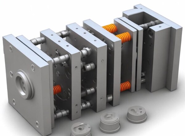
Introduction: The plastic mold has two parts: the movable mold and the fixed mold. The movable mold is on the movable template of the injection molding machine, and the fixed mold is on the fixed template of the injection molding machine. When you do injection molding, you close the movable mold and the fixed mold to make a pouring system and a cavity.

When the mold is opened, the movable mold and the fixed mold are separated in order to take out the plastic product.The structure of the mold may vary depending on the type and properties of the plastic, the shape and structure of the plastic product, and the type of injection machine, but the basic structure is the same.

The mold is mainly composed of a gating system, a temperature control system, a molding part, and a structural part.This article mainly introduces the components of injection molds.mold manufacturing process improves product quality. This article analyzes the composition of the mold.

Injection Mold Structure is Divided by Function
Made up of: pouring system, temperature control system, molding parts system, exhaust system, guide system, ejection system, etc.Among them, the pouring system and molding parts are the parts that are in direct contact with the plastic, and change with the plastic and the product. They are the most complex and most variable parts in the mold, requiring the highest processing finish and precision.
Gating System
Refers to the flow channel part before the plastic enters the cavity from the nozzle, including the main channel, cold material hole, diverter channel, and gate, etc.The gate system is the flow channel of plastic material in the injection mold, which directly affects the filling effect and the quality of plastic parts. The gate system includes the main runner, the branch runner, the gate, and the cold well.
The main runner and the branch runner are used to guide the molten plastic material to the filling part of the mold. The gate is the entrance of the plastic material from the injection molding machine into the mold. The cold well is used to collect excess plastic material to prevent defects in molded parts.

Main Runner
It is a section of the mold that connects the injection machine nozzle to the branch runner or cavity. The top of the main runner is concave to connect with the nozzle. The main runner inlet diameter should be slightly larger than the nozzle diameter (0.8mm) to avoid overflow and prevent the two from being blocked due to inaccurate connection.
The inlet diameter depends on the size of the product, generally 4-8mm. The main runner diameter should be expanded inward at an angle of 3° to 5° to facilitate the demolding of runner debris.

It is a hole at the end of the main runner to capture the cold material generated between two shots at the end of the nozzle, thereby preventing the blockage of the branch runner or gate. If the cold material is mixed into the cavity, internal stress is easily generated in the molded part. The diameter of the cold slug hole is about 8-10mm and the depth is 6mm.
In order to facilitate demolding, its bottom is often supported by the demolding rod. The top of the demolding rod should be designed as a zigzag hook or a sunken groove so that the main channel protrusion can be pulled out smoothly during demolding.

Cold Slug Hole
It is a hole at the end of the main channel to catch the cold slug that is generated between two shots at the end of the nozzle, so that the branch channel or gate does not get blocked. If the cold slug gets mixed into the cavity, it is easy to generate internal stress in the molded product. The diameter of the cold slug hole is about 8-10mm and the depth is 6mm.
To make it easier to remove the mold, the bottom of the mold is often supported by a mold release rod. The top of the mold release rod should be designed with a zigzag hook or a sunken groove so that the main channel protrusion can be easily pulled out when the mold is removed.

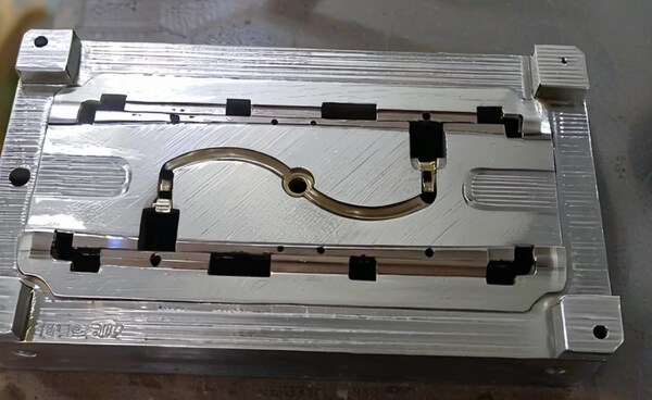
Branch Channel
It’s a channel that connects the main channel and each cavity in a multi-cavity mold. In order to make the molten material fill each cavity at the same speed, the branch channels on the mold should be arranged symmetrically and equidistantly.The shape and size of the runner cross section have an impact on the flow of plastic melt, product demolding, and the difficulty of mold manufacturing.
If we consider the flow of equal material volume, the runner with a circular cross section has the smallest resistance.However, because the cylindrical runner has a small specific surface area, it is not good for cooling the runner projections. This runner must be opened on both halves of the mold, which is labor-intensive and easy to align.
Therefore, trapezoidal or semicircular runners are often used, which are opened on one half of the mold with a demolding rod. The runner surface must be polished to reduce flow resistance and provide a faster filling speed.
The size of the runner depends on the type of plastic, the size and thickness of the product. For most thermoplastics, the cross-sectional width of the runner does not exceed 8mm, the largest can reach 10-12mm, and the smallest is 2-3mm.The cross-sectional area should be minimized as much as possible while meeting the needs to avoid increasing the runner protrusions and prolonging the cooling time.

Gate
It’s a channel that connects the main channel (or runner) and the cavity. The cross-sectional area of the channel can be the same as that of the main channel (or branch channel), but it is usually smaller. So it’s the smallest part of the entire runner system. The shape and size of the gate have a big impact on the quality of the product.
The function of the gate is to control the flow rate, prevent the melt stored in this part from solidifying too early and flowing back, and increase the temperature of the melt passing through by strong shear, so as to reduce the apparent viscosity, improve the fluidity, and facilitate the separation of the product from the runner system.

The shape, size, and location of the gate depend on the properties of the plastic, the size and structure of the part. Generally, the gate has a rectangular or circular cross-section, with a small cross-sectional area and a short length.
This is not only because of the above functions, but also because it is easier for a small gate to become larger, while it is difficult for a large gate to become smaller. The gate location should generally be selected where the part is thickest without affecting the appearance. The gate size should be designed to take into account the properties of the plastic melt.

It’s the space in the mold for molding plastic products. The components used to form the cavity are collectively referred to as molding parts.Each molding part often has a special name. The molding parts that constitute the appearance of the product are called concave molds (also called female molds), and the parts that constitute the internal shape of the product (such as holes, grooves, etc.) are called cores or punches (also called male molds).
When designing molding parts, the overall structure of the cavity should be determined first according to the performance of the plastic, the geometric shape of the product, the dimensional tolerance and the use requirements.

Next, you need to decide where to put the parting line, gate, and vent, and how to take the part out. Then, you need to decide how to design each part and how to put them together based on the size of the part you’re making. The plastic is under a lot of pressure when it goes into the mold, so you need to pick the right parts and make sure they’re strong enough and stiff enough.
To make sure the plastic product is smooth and beautiful, and easy to demold, the roughness Ra of the surface in contact with the plastic should be greater than 0.32um, and it should be corrosion-resistant. The molded parts are generally heat treated to increase hardness and are made of corrosion-resistant steel.

Exhaust Port
It is a slot-shaped air outlet opened in the mold to discharge the original gas and the gas brought in by the molten material. When the molten material is injected into the cavity, the air originally stored in the cavity and the gas brought in by the melt must be discharged to the outside of the mold through the exhaust port at the end of the material flow .
Otherwise the product will have pores, poor welding, incomplete mold filling, and even the accumulated air will burn the product due to high temperature generated by compression.Usually, the vent can be placed at the end of the flow of molten material in the cavity or on the parting surface of the mold. The latter is to open a shallow groove with a depth of 0.03-0.2mm and a width of 1.5-6mm on one side of the die.

During injection, there will not be much molten material seeping out of the vent, because the molten material will cool and solidify there to block the channel.Don’t open the exhaust port towards yourself, or you might get sprayed with molten material and get hurt. You can also use the clearance between the ejector rod and the ejector hole, the clearance between the ejector block and the stripper plate and the core to exhaust.
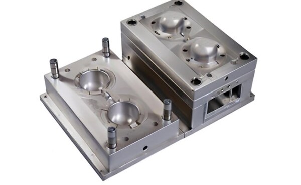
Molding Parts System
It refers to the combination of various parts that make up the shape of the product, including the movable mold, the fixed mold, and the cavity (die), the core (convex mold), the molding rod, etc.The core forms the inner surface of the product, and the cavity (die) forms the outer surface shape of the product. After the mold is closed, the core and cavity make up the mold cavity.

Sometimes, according to the process and manufacturing requirements, the core and die are made up of several pieces, sometimes they are made as a whole, and inserts are only used in parts that are easy to damage and difficult to process.
The mold part system includes components such as inclined tops and sliders, which are core components for the shape and structure of mold parts, and the filling and cooling of plastic materials are achieved through closing and separation.Inserts are used for special shapes and processing requirements of mold parts, such as threaded holes and grooves, while inclined tops and sliders are used to achieve the inclination and complex shapes of mold parts.

The molding part has a core and a die. The core makes the inside of the product, and the die makes the outside shape of the product. After the mold is closed, the core and cavity make the mold’s cavity. Sometimes the core and die are made of several pieces, sometimes they are made as one piece, and inserts are only used in parts that are easy to break and hard to make.
The exhaust port is a slot-shaped outlet opened in the mold to let out the original gas and the gas brought in by the molten material.

When the molten material is injected into the cavity, the air originally stored in the cavity and the gas brought in by the molten material must be let out to the outside of the mold through the exhaust port at the end of the material flow, otherwise the product will have holes, poor connection, incomplete mold filling, and even the accumulated air will be compressed to generate high temperature and burn the product.
Usually, the exhaust port can be placed at the end of the molten material flow in the cavity or on the parting surface of the mold.The latter is a shallow groove with a depth of 0.03-0.2mm and a width of 1.5-6mm opened on one side of the die. During injection, there will not be much molten material seeping out of the exhaust port, because the molten material will cool and solidify there and block the channel.

The exhaust port should not be opened facing the operator to prevent the molten material from accidentally spraying out and injuring people. In addition, the clearance between the ejector rod and the ejector hole, the clearance between the ejector block and the stripper plate and the core, etc. can also be used to exhaust.
Temperature Control System
To meet the temperature requirements of the injection process, you need a temperature control system to adjust the mold temperature. For thermoplastic injection molds, the main thing is to design a cooling system to cool the mold (the mold can also be heated).

The common method of mold cooling is to open a cooling water channel in the mold and use circulating cooling water to take away the heat of the mold; in addition to using cooling water to pass hot water or hot oil, the mold can also be heated by installing electric heating elements inside and around the mold.
The temperature control system is used to control the working temperature of the mold to ensure the quality and production efficiency of the molded parts. The temperature control system includes components such as waterways, water wells, waterway nozzles, spiral waterways, heating rods, and cooling rods.

The waterway and water well are used to circulate cooling water to control the mold temperature. The waterway nozzles and spiral waterways are used to enhance the cooling effect. The heating rods and cooling rods are used to adjust the heating and cooling speed of the mold.
Structural Parts
It refers to the various parts that make up the mold structure, including: guide posts, ejector pins, core pulling and various parts of the parting line. Such as front and rear clamping plates, front and rear buckle templates, pressure plates, pressure columns, guide columns, stripping plates, stripping rods and return rods.

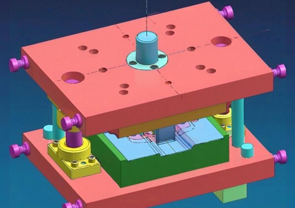
Guide Components
To make sure the movable mold and the fixed mold can be aligned accurately when the mold is closed, guide components must be set in the mold. In the injection mold, four sets of guide columns and guide sleeves are usually used to form the guide.Sometimes, inner and outer conical surfaces that match each other are set on the movable mold and the fixed mold to help with positioning.

Ejection Mechanism
When you open the mold, you need something to push or pull the plastic part and the water out of the runner. The push plate and the ejector plate are used to hold the ejector rod. The reset rod is usually fixed in the ejector rod, and the reset rod resets the push plate when the movable and fixed molds are closed.

Side Core Pulling Mechanism
Some plastic products with side recesses or side holes need to be parted sideways before being pushed out. After the side core is pulled out, they can be demolded smoothly. At this time, a side core pulling mechanism needs to be set in the mold.
Standard Mold Frame
To reduce the heavy workload of mold design and manufacturing, most injection molds use standard mold frames.

The Exhaust System
The purpose of the exhaust system is to remove air from the cavity and the gas generated by the melted plastic during the injection molding process. If the exhaust is not smooth, the surface of the product will have gas marks, burns, and other defects.The exhaust system of the injection mold is usually a groove-shaped outlet opened in the mold to exhaust the air in the original cavity and the gas brought in by the molten material.
When the hot stuff goes into the hole, the air that was already in the hole and the air that came in with the hot stuff have to get out of the hole at the end of the hole where the hot stuff goes, or else the thing you make will have holes, not stick together good, not fill up all the way, and maybe the air that gets stuck will get squished and get hot and burn the thing you make.
Usually, you can put the hole where the hot stuff goes into the hole or on the place where the two parts of the hole come apart.The second is to open a shallow groove with a depth of 0.03-0.2mm and a width of 1.5-6mm on one side of the concave mold. During injection, not much molten material will seep out of the exhaust hole, because the molten material will cool and solidify there and block the channel.
The exhaust port should not be opened facing the operator to prevent the molten material from accidentally spraying out and injuring people. In addition, the clearance between the ejector rod and the ejector hole, the clearance between the ejector block and the stripper plate and the core can also be used to exhaust.

The exhaust system is used to remove the gas generated during the injection molding process to prevent bubbles and defects. The exhaust system includes ejector pin exhaust, parting surface exhaust, exhaust needle exhaust and exhaust hole exhaust.Reasonable design and layout of the exhaust system can effectively improve the quality and appearance of molded parts. Choose Zetar Mold for production and processing, the technology is guaranteed, and the delivery cycle meets customer needs.
The Guide System
The Guide Systemis set up to make sure that the movable mold and the fixed mold can be accurately aligned when the mold is closed, and a guide component must be set in the mold.In the injection mold, four sets of guide pins and guide sleeves are usually used to form the guide component. Sometimes, inner and outer cones that match each other are set on the movable mold and the fixed mold to help with positioning.

The guide positioning system is used to make sure the mold is in the right place and moves the right way when it’s working. It has guide pins and guide sleeves, conical positioning blocks, and zero-degree positioning blocks.
Guide pins and guide sleeves are the main parts of the mold positioning system. They make sure the mold is in the right place by fitting together really well. Conical positioning blocks and zero-degree positioning blocks are used to make sure the mold lines up by itself and to make sure it lines up really well.

Ejector System
Usually includes: ejector pins, front and rear ejector pin plates, ejector pin guide rods, ejector pin return springs, ejector pin plate locking screws and other parts. When the product is formed and cooled in the mold, the front and rear molds of the mold are separated and opened, and the ejector pins are ejected in the injection mold.
The ejector of the molding machine pushes or pulls the plastic product and the condensate in the flow channel out of the mold cavity and flow channel position for the next injection molding cycle.

The ejector system is a system used to eject the molded parts from the mold, including ejector pin ejection, push plate ejection, and other methods. The design and selection of the ejector system are determined according to the shape, material, and size of the molded parts to ensure the integrity of the molded parts and the ejection effect.
Injection Molds are Divided by Structure
Mold frames, mold cores, auxiliary parts, auxiliary systems, auxiliary settings, dead corner processing mechanisms, and other parts are generally what make up injection molds.

Mold Frame
Usually, we don’t have to design it, and we can buy it directly from the standard mold base manufacturer, which saves a lot of time to design the mold, so it is called the standard mold base for injection molds. It is the most basic part of the injection mold.
Mold Core
The mold core is the most important part of the mold. It is where the plastic product is formed and where most of the processing time is spent. However, some molds, unlike more simple molds, don’t have a core. The product is formed directly on the template. Most of the early injection molds were like this, which was relatively backward.
Auxiliary Parts
The auxiliary parts commonly used in injection molds include positioning rings, sprue bushings, ejectors, puller pins, support columns, ejector plate guide columns and guide sleeves, trash nails, etc. Some of them are standard parts and can be ordered directly when ordering the mold frame, and some need to be designed by yourself.
Auxiliary System
The auxiliary systems of injection molds are as follows: pouring system, ejection system, cooling system, and exhaust system. Sometimes, because the temperature of the plastic material used needs to be heated to a very high temperature, some molds will also have a heating system.

Auxiliary Settings
The auxiliary settings of injection molds include eyelet holes, KO holes (ejector rod holes), etc.
Dead Corner Processing Structure
When the plastic product has a dead corner, the mold will also have one or more structures to handle the dead corner. Such as sliders, inclined ejectors, hydraulic cylinders, etc. In most domestic books, this mechanism for handling dead corners is called “core pulling mechanism”.

Injection Mold Components
Nozzle System
The nozzle system is used to inject molten plastic into the mold to achieve product molding. It includes components such as nozzles and nozzle tips. It controls the opening and closing of the nozzle and the flow of molten plastic to achieve product injection molding. The nozzle system needs to have good sealing and wear resistance to ensure the normal injection of plastic and the quality of the product.

Mold Seat
The mold seat is the basic part of the injection mold, which supports and fixes the whole mold structure. It is usually made of high-quality alloy steel and has enough strength and rigidity to bear the pressure and extrusion during the injection molding process.

Ejector System
The ejector system is used to eject the molded product from the mold. It includes components like ejector rods and ejector plates, and the ejection of the product is achieved through the movement of the ejector rod. The ejector system needs to have enough strength and stability to make sure the ejection effect and production efficiency of the product.

Fixed Plate
The fixed plate is located above the mold base and is used to fix the various components of the mold. It is usually made of high-quality alloy steel and has enough strength and rigidity to make sure the mold is stable and rigid during the injection molding process.

Cooling System
The cooling system is used to control the temperature of the mold to ensure the quality of the product and the efficiency of production. It includes components such as cooling water channels and cooling devices, which absorb heat from the mold through circulating cooling water. The cooling system needs to be designed reasonably to ensure uniform cooling of all parts of the mold to avoid stress and deformation.
Core and Cavity
The core and cavity are the most important parts of the injection mold. They determine the shape and size of the final product. The core is the inside part of the product, and the cavity is the outside shape of the product. The core and cavity are usually made of high-quality tool steel or high-speed steel. They are machined and heat-treated to make them hard and wear-resistant.

Slider System
The slider system is used to make complex product structures and internal cavities. It has parts like sliders, guide pins, guide sleeves, etc. that make the mold open and close and move by sliding or rotating. The slider system needs to be very precise and stable to make sure the product shape and size are right.
Structural Composition of Injection Molding Machines
A general-purpose injection moulding machine has an injection device, mold clamping device, hydraulic transmission system, and electrical control system. The injection device’s main job is to melt the plastic and inject a certain amount of molten material into the mold cavity with enough pressure and speed. The injection device is made up of plasticizing components (screw, barrel, and nozzle), hopper, transmission device, metering device, injection and moving cylinders, and so on.

Mold Clamping Device
The mold clamping device is responsible for opening and closing the mold, ensuring that the mold is securely closed during injection, and ejecting the product. The mold clamping device mainly consists of front and rear fixed templates, movable templates, tie rods that connect the front and rear templates, mold clamping cylinders, connecting rod mechanisms, mold adjustment devices, and product ejection devices.
Hydraulic System and Electrical Control System
Its job is to make sure the injection molding machine works right and good like it’s supposed to (pressure, speed, temperature, time) and does the steps of the process in the right order.

The hydraulic system of the plastics injection molding machine is made up of different hydraulic parts and pipes and other stuff that helps it work, and the electrical control system is made up of different electrical things and tools. The hydraulic system and the electrical system work together to give the injection molding machine power and control.
Conclusion
Injection molds are made up of several core parts, mainly including mold base, ejector system, fixed plate, slide system, core and cavity, cooling system and nozzle system.The mold base supports the whole structure, the ejector system pushes the finished product out, the fixed plate stabilizes the components, the slide system handles complex shapes, the core and cavity define the product shape, the cooling system adjusts the temperature, and the nozzle system injects the plastic.

In addition, it also includes the temperature control system, exhaust system, guide system and ejection system, which are used to control the mold temperature, exhaust gas, accurately position the mold and eject the product.
mold manufacturing process improves product quality , In the injection mold, the injection unit injects the molten plastic into the mold through the injection molding screw and enters the cavity through the sprue bushing, ensuring the precise molding and high quality of the product.

The collaborative work of these components ensures the smooth progress of the plastic injection molding process and the high quality of the final product.


