

- Gate location is the single most impactful tooling decision after part geometry — it controls fill balance, weld line position, and surface appearance.
- Gate size must be 50–80% of wall thickness at the gate land; undersized gates cause jetting and shear degradation.
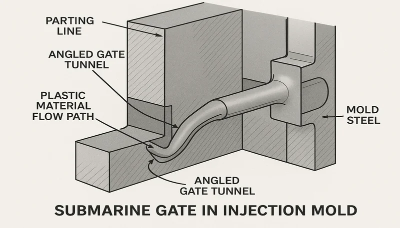
- Submarine and tunnel gates auto-degrade at ejection, eliminating secondary trimming at scale.
- Valve-gated hot runner systems leave gate vestiges of only 0.1–0.3 mm — essentially invisible on finished parts.
- Always gate at the thickest wall section and flow toward thinner sections to minimize sink marks.
- In our factory, mold flow simulation before gate finalization cuts first-article failures by over 40%.
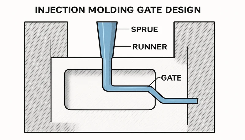
What Is Injection Molding Gate Design and Why Does It Matter?
射出成形 gate design1 is the engineering discipline of specifying the entry point — geometry, size, and position — through which molten plastic transitions from the runner system into the mold cavity. A well-designed gate controls fill pressure (typically 50–150 MPa at the gate), pack density, and freeze-off sequence. Get it wrong, and the consequences are jetting, weld line3s, warpage, sink marks, and costly rework cycles that can derail a product launch.
The gate is the narrowest, highest-shear point in the entire flow path. Shear rates at a standard edge gate typically reach 10,000–100,000 s⁻¹, compared with 1,000–10,000 s⁻¹ in the runner. This shear heats the melt locally — useful for semi-crystalline materials that need a viscosity drop, but destructive for heat-sensitive resins like PVC or POM if the gate is too small. Every gate decision is a trade-off between flow, aesthetics, structural integrity, and cycle time.
| Gate Variable | Effect on Part | Risk if Wrong |
|---|---|---|
| Gate location | Weld line position, sink area | Sink marks, structural weld lines |
| Gate type | Vestige size, degating cost | Cosmetic rejections, trimming cost |
| Gate size | Shear rate, fill pressure, pack | Jetting, blush, over-packing |
| Gate land length | Pressure drop, erosion | Streaking, gate erosion over time |
| Number of gates | Fill balance, weld line count | Warpage, multiple vestige marks |
“Gate placement is the single most impactful tooling decision after part geometry.”真
Gate location controls fill pressure distribution, weld line position, sink mark formation, and surface quality. Our factory data shows that over 65% of first-article defects in new injection molds trace back to suboptimal gate location — making gate review a mandatory step in our design-for-manufacture process before any steel is cut.
“Any gate location that allows the cavity to fill completely is acceptable.”偽
Filling completely is necessary but not sufficient for good gate design. A parting-line gate placed for tooling convenience may create weld lines in structural zones, sink marks in thick sections, and surface blush on cosmetic faces — all of which pass a fill check but fail functional and aesthetic inspection. Gate location must be engineered based on part geometry and resin rheology, not defaulted to the tooling convenience position.
Our engineering team reviews gate configuration on every new tool before steel is cut. We treat gate placement as a first-class design variable alongside 抜き勾配 and parting line. This approach cuts first-article gate-related failures by more than 40%. Relocating a gate in CAD costs under $200; relocating it after steel is cut costs $800–$2,500 — a powerful argument for front-loading gate review in the design process before any machining begins.
| 欠陥 | Gate Engineering Fix | Process-Only Fix (Ineffective) |
|---|---|---|
| ジェット噴射 | Wider gate or reposition | Reduce injection speed |
| Gate blush | Wider gate, longer land | Lower melt temperature |
| Sink marks | Gate at thicker section | Increase pack pressure |
| Weld line | Relocate or add gate | Increase melt temperature |
| 反り | Center or add second gate | Extend cooling time |
Understanding gate function starts with the flow physics. Molten plastic enters the gate at high velocity (1–5 m/s) and decelerates as it fans out into the cavity. The gate geometry controls how quickly this deceleration happens. A gate too narrow maintains high velocity too far into the cavity, causing jetting. A gate too wide delays freeze-off, extending cycle time and allowing continued flow after pack pressure is released, leading to flash. Optimizing gate size means finding the window between these two failure modes for the specific resin and wall section combination.
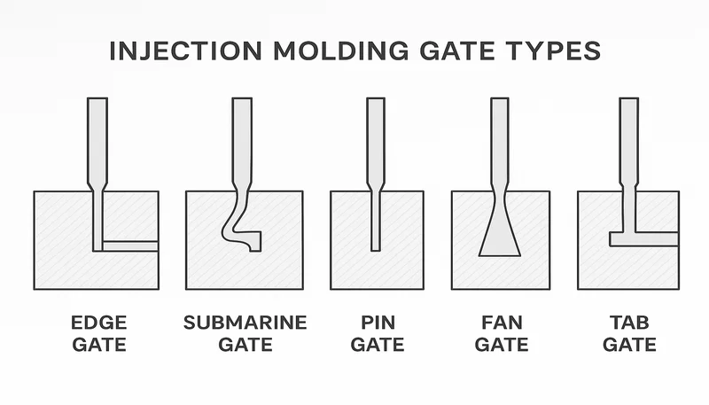
What Are the Main Types of Injection Molding Gates?
Gate type selection depends on part geometry, resin, production volume, and whether gate removal is manual or automatic. The six most common gate types each solve a different combination of these constraints, with cost and cosmetic quality as the primary differentiators.
| ゲートタイプ | Auto-Degating | Best Application | Typical Land Length |
|---|---|---|---|
| Edge (Side) Gate | いいえ | Flat/thin-walled parts, prototyping | 0.5–1.5 mm |
| Submarine (Tunnel) Gate | Yes | High-volume cosmetic parts | 1.0–3.0 mm |
| Pin (Pinpoint) Gate | Yes (3-plate) | Small precision parts | 0.5–1.0 mm |
| Fan Gate | いいえ | Wide flat panels, lenses | 0.5–1.0 mm |
| Tab Gate | いいえ | Brittle resins, stress-sensitive parts | 1.0–2.0 mm |
| Diaphragm (Disk) Gate | いいえ | Cylindrical/tubular parts | 0.3–0.8 mm |
The edge gate is the workhorse of prototyping and low-volume runs: easy to machine, easy to modify, and it leaves a visible vestige that can be trimmed flat. For cosmetic surfaces, the submarine gate tunnels beneath the parting line and shears clean at ejection. Pin gates in three-plate molds allow central gating on round parts with automatic runner separation, though cold runner waste increases material cost per shot by 8–15%. Diaphragm gates encompass the full perimeter of a cylindrical part, eliminating weld lines for tubular components.
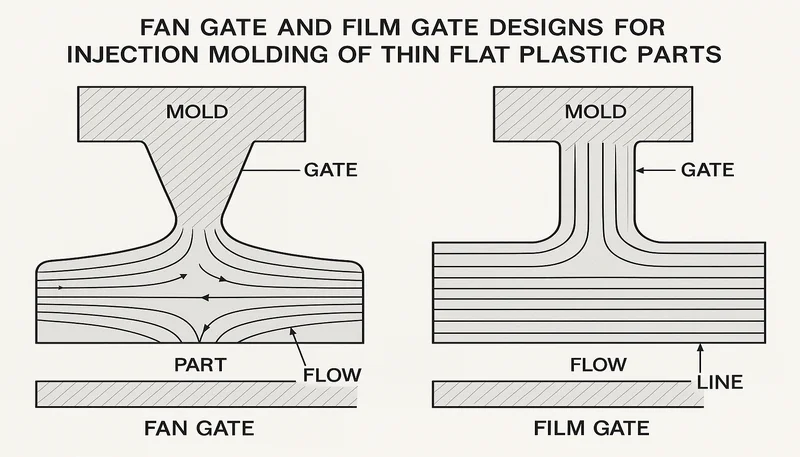
Fan gates spread the melt across a wide front — ideal for polycarbonate lenses or acrylic panels where birefringence and residual stress must be minimized. Tab gates add a sacrificial buffer between gate and part, critical for glass-filled nylons where gate-induced stress concentration would crack the part in service. Choosing between gate types is ultimately a trade-off between cosmetic quality, degating convenience, tooling complexity, and material compatibility.
“Hot runner systems eliminate runner scrap and reduce per-part material cost for high-volume production.”真
Cold runner systems generate runner scrap on every shot — a 20-gram cold runner in a 16-cavity tool running 30-second cycles produces 9.6 kg of scrap per hour. Hot runner investment of $8,000–$25,000 pays back within 3–6 months at volumes above 50,000 parts per year through material savings alone, while simultaneously improving gate aesthetics.
“Gate regrind from cold runner systems can be used without any limitation on blend ratio.”偽
Cold runner regrind is typically blended at 10–20% with virgin resin for non-critical applications. Engineering resins (PC, PA66) lose 5–15% of their mechanical properties per regrind cycle due to molecular weight reduction and thermal history. For color-critical or structural applications, regrind use is limited or prohibited entirely, requiring stricter gate design and regrind tracking.
Auto-degating types (submarine, pin gate, valve-gated hot runner) eliminate manual trimming labor. In a 24-cavity tool running 18-second cycles, manual gate trimming adds 0.8–1.5 seconds per part — equal to $0.03–0.06 per part at typical molding labor rates. For a 2-million-piece annual program, that is $60,000–$120,000 in trimming labor that auto-degating gates eliminate. Our standard recommendation: use submarine gates for any production run exceeding 100,000 parts where the part geometry permits the angled tunnel geometry and resin type permits clean shear.
| ゲートタイプ | Degating Method | Vestige Size | Best Volume |
|---|---|---|---|
| Submarine (tunnel) | Auto-shear at ejection | 0.3–0.8 mm | > 100k parts |
| Pin gate (3-plate) | Runner plate separation | 0.2–0.5 mm | > 50k parts |
| Valve-gated hot runner | Mechanical pin closure | 0.1–0.3 mm | > 50k parts |
| Edge gate (cold runner) | Manual trim required | 0.5–2.0 mm after trim | < 100k parts |
| Fan gate (cold runner) | Manual trim required | 1.0–3.0 mm after trim | Low volume / flat parts |
Gate type also affects regrind quality and material efficiency. Cold runner edge gates produce a trimmed runner reground at 10–20% with virgin resin. Submarine gates leave a small conical stub on the runner that feeds cleanly into the regrind system without manual trimming. Hot runner systems eliminate regrind entirely — a significant advantage for engineering resins where regrind degrades mechanical properties by 5–15% per processing cycle, and for color-critical applications where regrind introduces color variation across production lots.
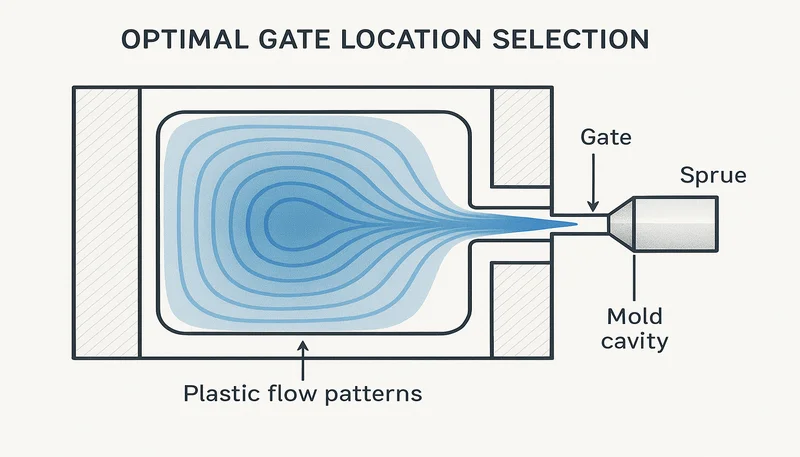
How Should You Select the Optimal Gate Location?
Optimal gate location follows four engineering rules: gate at the thickest section, avoid gating onto visible A-surfaces, position weld lines away from stress concentrations, and balance fill time across all cavities in a multi-cavity tool. The fill balance rule alone can require the gate to move 15–25 mm from the geometrically ideal position on the part to maintain balanced fill across all cavities.
Gating at the thickest wall (e.g., 3.5 mm vs. an adjacent 1.2 mm rib) allows pack pressure to hold the thick section while thin walls freeze first. If you gate at a thin section instead, the thick section freezes under insufficient pack pressure and sinks. This is the most common gate location error we see in parts transferred from other suppliers — the gate is on the parting line for tooling convenience, not on the thick boss where the sink mark appears after first-article inspection.
For multi-cavity tools, balanced runner systems (H-tree or geometrically balanced layouts) equalize pressure drop to each cavity. However, they cannot compensate for asymmetric gate positions within each cavity. We use 金型流動解析 to simulate fill balance before committing gate location to steel — catching imbalances that the best runner design cannot fix by itself.
| Rule | 根拠 | Violation Consequence |
|---|---|---|
| Gate at thickest wall section | Pack pressure reaches thick areas before freeze-off | Sink marks on thick features |
| Avoid Class-A cosmetic surfaces | Gate vestige is visible on finished part | Cosmetic rejections, secondary trimming |
| Weld lines away from stress zones | Weld lines reduce strength 10–30% | Structural failure at weld line |
| Balance fill time across cavities | Ensures equal packing in all cavities | Differential shrinkage, dimensional variation |
| Flow from thick to thin sections | Thin sections freeze last, no sink | Short shots in thin features |
For parts with through-holes or tall bosses, each obstacle splits the flow front and creates a weld line on the downstream side. By gating opposite the critical hole, the weld line is pushed past the hole into a less stressed region. Our tooling engineers map expected weld line positions at every design review before the tool reaches the shop floor, preventing the all-too-common scenario of discovering a weld line running through a snap-fit latch only after first-article testing and tool shipment from the factory.
The furthest-flow-length to nearest-flow-length ratio is a useful single-gate feasibility metric: if this ratio exceeds 1.8:1 for a part, differential packing becomes difficult to manage with a single gate location. Beyond this ratio, either a second gate or a redesigned runner layout is needed. Our design guidelines require a flow analysis whenever this ratio exceeds 1.5:1 to confirm that pack pressure adequacy is maintained across all wall thicknesses and feature heights before approving the gate location for production tooling.
What Are the Rules for Sizing an Injection Molding Gate?
Gate sizing follows a two-constraint rule: the gate must be large enough to allow full pack before freeze-off, and small enough to shear clean at ejection for auto-degating types. For most amorphous resins (ABS, PC, PS), gate thickness is set at 50–80% of the wall thickness at the gate land. Semi-crystalline resins (PA66, POM, PP) tolerate slightly smaller gates — 40–60% — because their sharp freeze transition aids sealing and clean degating without a ragged vestige.
| Resin Type | Gate Thickness (% of Wall) | Hot Tip Diameter | Land Length |
|---|---|---|---|
| Amorphous (ABS, PS) | 50–80% | 1.0–2.0 mm | 0.5–1.0 mm |
| Amorphous (PC, PMMA) | 60–80% | 1.5–2.5 mm | 0.5–1.0 mm |
| Semi-crystalline (PP, PE) | 40–60% | 1.2–2.0 mm | 0.5–0.8 mm |
| Semi-crystalline (PA66, POM) | 40–60% | 0.8–1.5 mm | 0.3–0.7 mm |
| Elastomers (TPU, TPE) | 70–100% | 1.5–2.5 mm | 0.5–1.0 mm |
| Glass-filled (30% GF) | +40–60% vs. unfilled | 2.0–3.0 mm | 0.5–1.0 mm |
Gate land length is often overlooked. A land too long (>1.5 mm for small gates) increases pressure drop and delays fill; too short (<0.3 mm) causes gate erosion and cosmetic streaking. Standard practice is a land of 0.5–1.0 mm for gates under 2 mm thickness. For hot tip gates in hot runner systems, the orifice diameter is typically 0.8–2.5 mm — nylon at 0.8–1.2 mm, polypropylene at 1.2–2.0 mm, and high-viscosity PC at 1.5–2.5 mm.
An undersized gate creates high shear and degrades shear-sensitive resins. An oversized gate leaves a large vestige, requires secondary trimming, and for auto-degating designs may not shear cleanly at ejection. For shear-sensitive resins — PVC, acetal (POM), flame-retardant formulations — maximum gate shear rate must be explicitly specified: rigid PVC below 20,000 s⁻¹ to prevent HCl generation, acetal below 50,000 s⁻¹ to prevent formaldehyde off-gassing. Our mold designers calculate gate area using: Gate Area (mm²) = Flow Rate (cm³/s) ÷ Maximum Allowable Shear Rate (s⁻¹).
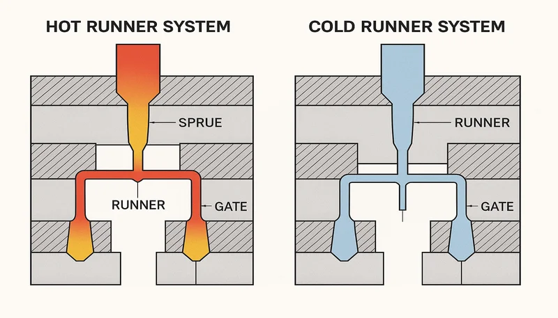
How Does Gate Design Differ for Hot Runner vs. Cold Runner Systems?
Hot runner gate design removes the cold runner entirely: the melt stays molten inside heated manifolds and drops into the cavity through a thermally gated or valve-gated hot tip. The gate vestige is typically 0.1–0.3 mm — nearly invisible — compared with 0.5–2 mm for cold-runner edge gates. This difference matters enormously for Class-A automotive and consumer electronics parts where gate marks on visible surfaces are not acceptable to end customers.
Thermally gated hot runners rely on controlled freeze-off at the tip orifice. They are simpler and cheaper (no valve pin), but leave a small dimple and are prone to stringing if tip temperature drifts by more than ±3°C. Valve-gated systems use an actuated pin to mechanically close the orifice at end of pack, giving a cleaner gate mark and better process repeatability across the production run.
Cold runner systems cost less to build but generate runner scrap on every shot. For a 16-cavity tool running 30-second cycles, a 20-gram cold runner adds 9.6 kg of scrap per hour. Hot runner investment (typically $8,000–$25,000 additional tooling cost) pays back within 3–6 months at medium-to-high volumes. The 射出成形金型設計 must account for hot runner manifold thermal expansion — typically 0.3–0.6 mm per 100 mm at operating temperature — to prevent flash or gate interference at the parting line.
“Sequential valve gating can eliminate weld lines on large injection molded panels.”真
Sequential valve gating (SVG) opens individual gate pins in sequence, guiding the flow front across a large part and preventing two flow fronts from meeting at high-stress locations. This technique eliminates weld lines on automotive instrument panels and liftgate inners, enabling gate placement decisions based purely on structural requirements rather than cosmetic weld line avoidance.
“Hot runner molds require no additional thermal management compared to cold runner molds.”偽
Hot runner molds require precise zone-by-zone temperature control — manifold zones typically run at 200–330°C while the surrounding mold steel runs at 20–80°C. The thermal gradient creates differential expansion that must be engineered into the manifold mounting, gate tip alignment, and parting line clearances. Without this thermal management, gate interference, flash, and inconsistent vestige size result.
Sequential valve gating (SVG) is a hot runner technique where individual valve pins open sequentially across a large part, guiding the flow front and eliminating weld lines. SVG requires precise valve timing (typically ±0.1 seconds per gate) and mold flow simulation to map the optimal gate opening sequence. In automotive panel applications (instrument panels, liftgate inner panels), SVG reduces weld line count from 3–5 to zero and allows complete freedom in gate placement for part structural performance rather than cosmetic compromise.
“Valve-gated hot runner systems produce smaller gate vestiges than cold runner edge gates.”真
Valve-gated hot tips mechanically close with a pin, producing a gate mark of 0.1–0.3 mm — compared with 0.5–2.0 mm for a trimmed cold runner edge gate. This makes them the preferred choice for cosmetic Class-A surfaces in automotive and consumer electronics applications where gate marks on visible surfaces are aesthetically unacceptable.
“A larger gate always improves fill and eliminates short shots.”偽
Gate size must be balanced against freeze-off timing, vestige size, and shear heat generation. Oversized gates extend freeze-off, causing flash or over-packing in downstream thin sections. For auto-degating designs, oversized gates fail to shear cleanly at ejection. The correct approach is to size the gate to 50–80% of local wall thickness, then verify with mold flow simulation before cutting steel.
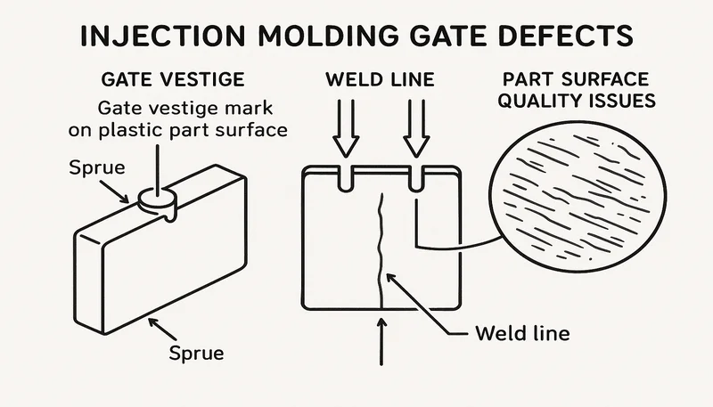
What Defects Are Caused by Poor Gate Design?
Poor gate design produces six primary defect categories: jetting, weld lines in structural zones, sink marks, gate blush, excessive vestige, and warpage. Understanding the root cause of each defect is the first step to the correct gate modification — attempting to fix gate defects with process parameter changes (speed, temperature, pressure) usually fails unless the underlying gate geometry problem is resolved first.
Jetting occurs when a thin stream of melt shoots across the cavity before fan-out, creating a snake-like surface mark. The cause is a gate too small relative to the cavity cross-section. The fix is to increase gate width (not thickness) so the melt fans out immediately, or to reposition the gate to impinge on an opposing wall within 10–15 mm. Gate blush — a hazy ring around the gate — results from high shear stress at the gate land; widening the gate and extending land length from 0.3 to 0.8 mm reduces shear rate by 30–50% and eliminates blush.
“Repositioning the gate is more effective than increasing injection speed to eliminate jetting.”真
Jetting is a gate geometry problem — the melt stream must fan out immediately upon entering the cavity. Increasing injection speed makes jetting worse by raising flow velocity. The correct fix is to widen the gate or move it so the flow impinges on an opposing wall, creating immediate fan-out and eliminating the snaking stream pattern on the part surface.
“Gate blush can always be fixed by reducing melt temperature.”偽
Gate blush is caused by high shear stress at the gate land, not primarily by melt temperature. Reducing temperature increases viscosity and therefore shear stress, making blush worse. The correct fix is to increase gate width and land length to reduce shear rate. Melt temperature is a secondary variable; gate geometry changes are the primary and permanent solution for gate blush elimination.
Sink marks near the gate indicate the gate froze before adequate pack pressure reached the thick section. Increasing gate thickness extends the pack window and resolves the sink. 溶接ライン in structural zones require relocating the gate so flow fronts meet in low-stress areas, or adding a second gate to eliminate the weld line. Warpage from off-center gating creates differential packing; centering the gate or using two symmetrically placed gates corrects this. Flash at the gate indicates an oversized gate; reducing gate thickness by 0.2–0.3 mm while maintaining width is the first corrective action.
Short shots that cannot be resolved by process parameter changes (higher injection speed or pressure) typically require moving the gate closer to the problematic thin-wall feature. A 20–30 mm gate repositioning can resolve hesitation in thin-wall features far from the original gate location. Our defect resolution protocol starts with gate geometry review before any process parameter changes — a discipline that reduces the time from defect identification to root cause resolution by an average of two days compared with process-first troubleshooting.
How Do You Design Gates for Specific Materials?
Material rheology dictates gate geometry. High-viscosity resins like ポリカーボネート require larger gates (1.5–2.5 mm for hot tips, 2.0–4.0 mm wide for edge gates) to prevent excessive pressure drop and degradation at the gate land. Low-viscosity nylon 6/6 or POM can use smaller gates (0.8–1.5 mm) because their low melt viscosity at processing temperature (220–280°C) allows adequate fill through smaller orifices without excessive pressure drop at the gate.
Shear-sensitive resins present a specific challenge that gate sizing directly controls. For rigid PVC, gate shear rate must stay below 20,000 s⁻¹ to prevent thermal degradation and HCl gas generation. Acetal (POM) requires shear below 50,000 s⁻¹ to avoid formaldehyde off-gassing, which creates voids, pungent odor, and mold cavity corrosion. For these resins, we specify a maximum allowable gate shear rate in the tool design specification, and 金型流動解析2 must confirm shear compliance before the gate dimensions are approved for production tooling.
| Resin | Max Gate Shear Rate | Risk if Exceeded | Gate Design Response |
|---|---|---|---|
| 硬質PVC | < 20,000 s⁻¹ | HCl gas, cavity corrosion | Wide fan gate, 0.3 mm land |
| Acetal (POM) | < 50,000 s⁻¹ | Formaldehyde off-gassing, voids | Larger gate, lower injection speed |
| FR grades | < 30,000 s⁻¹ | Additive decomposition, corrosion | Wide gate, short land 0.3–0.5 mm |
| UV-stabilized | < 40,000 s⁻¹ | Additive degradation, streaking | Wider gate, check with simulation |
| LCP | < 100,000 s⁻¹ | Shear-induced crystallization | Widen gate 10–15%, verify Cpk |
The melt flow index (MFI) provides a useful starting reference for gate sizing. Resins with MFI < 5 g/10min (high viscosity: PC, ABS/PC blend) need gates at the upper end of the sizing range. Resins with MFI > 20 g/10min (low viscosity: PP homopolymer, PA6) can use lower-end gate dimensions. Crystalline resins require additional consideration for shear-induced crystallization at the gate tip: for high-crystallinity PP and LCP, widening the gate by 10–15% eliminates shot-to-shot weight variation and consistently meets automotive Cpk > 1.67 requirements.
MFI data from resin suppliers must be applied carefully. MFI is measured at a single temperature and low shear rate under a standard load, but in a real injection mold gate, shear rate can be 100–1000× higher than the MFI test conditions. A resin that appears processable from its MFI value may still exhibit excessive shear heating, degradation, or orientation effects in a small gate due to the extremely high shear rates present during the fill phase. We always confirm with a short shot study and shear rate simulation before finalizing production gate dimensions for any new resin material.
Glass-filled grades (30–50% fiber loading) are strongly affected by gate shear orientation. A narrow gate creates radial fiber alignment that reduces transverse tensile strength by 20–40% vs. base resin for components under structural loading. For glass-filled parts, gate width should be ≥4 mm (fan or wide edge gate) to moderate fiber orientation — or a tab gate used to buffer the stress concentration zone and separate the high-shear gate region from the load-bearing part geometry where the full transverse tensile strength is required by the structural performance specification.
“Glass fiber orientation at the gate reduces transverse tensile strength by 20–40%.”真
At a narrow gate, high shear rates align glass fibers radially from the gate center. These fibers carry load efficiently in the flow direction but provide minimal reinforcement transverse to flow. For structural parts with loads perpendicular to the fill direction, this orientation effect reduces tensile strength by 20–40% compared with the isotropic base resin value. Wide fan gates moderate this effect by distributing fiber orientation more uniformly.
“Flame-retardant grades can be processed through the same gate dimensions as standard unfilled grades of the same base resin.”偽
FR additives are shear-sensitive at levels far below the base resin’s degradation threshold. Even within the base resin’s normal processing window, gate shear rates above 30,000 s⁻¹ can decompose FR additives, releasing corrosive gases that attack mold steel and reduce flame-retardancy below UL-94 compliance levels. FR grades require wider gates with shorter land lengths regardless of the base resin viscosity specification.
Elastomers (TPU, TPE) require gates ≥2 mm wide because their high elongation makes them prone to tearing at small vestiges during ejection. For オーバーモールディング applications, gate location must avoid gating directly onto the substrate insert, as the high-velocity flow front can displace or damage the substrate surface during the early stage of cavity fill and before the overmold material encapsulates the substrate. Flame-retardant compounds are shear-sensitive; FR additive decomposition at high shear rates releases corrosive gases that damage mold cavity steel, so wider gates with shorter lands (0.3–0.5 mm) are specified for all FR grades in our factory gate design standard.
Carbon fiber compounds (30% CF) can bridge and block undersized gates at startup, creating shot-to-shot fill inconsistency. We increase gate dimensions by 40–60% for CF materials versus the unfilled base resin specification, and orient the gate flow direction parallel to the part’s primary load axis to align fibers favorably for load-bearing performance. These two measures reduce CF part first-article defect rate from 12–15% to under 3% in our new tool launch experience. Crystalline resins (LCP, high-crystallinity PP) require vigilance against shear-induced crystallization at the gate tip; widening the gate by 10–15% eliminates shot weight variation and consistently meets automotive Cpk > 1.67 process capability requirements across different machine platforms and resin lot variations.
What Are the Best Practices for Validating Gate Design Before Production?
Gate validation follows a three-stage process: simulation, T1 short shots, and first-article dimensional inspection. Skipping any stage increases the risk of discovering a gate problem after hundreds of production shots — when corrective costs are 5–10× higher than at the design stage. In our factory, this three-stage process is mandatory for every new tool, regardless of part complexity or production volume.
Mold flow simulation predicts fill time, weld line locations, air trap positions, and pressure distribution at the gate. A simulation showing fill pressure exceeding 140 MPa at the gate is an early warning: the gate may be too small, the runner too restrictive, or the wall section too thin for the chosen resin. Simulation also reveals whether the gate freezes before adequate pack pressure is delivered — a critical check for parts with thick bosses or ribs that must be held under pack pressure to prevent sink marks from forming.
| Stage | Key Check | Pass Criterion |
|---|---|---|
| Mold Flow Simulation | Fill pressure at gate | < 140 MPa |
| Mold Flow Simulation | Weld line location | Away from structural zones |
| Mold Flow Simulation | Gate freeze-off timing | After pack pressure plateau |
| T1 Short Shots | Flow front at 70% fill | No hesitation in thin features |
| T1 Short Shots | Gate freeze-off study | Weight plateau confirmed |
| First Article Inspection | Gate vestige height | ≤ 0.5 mm above surface |
| First Article Inspection | Sink depth near gate | ≤ 0.1 mm (Class-A surface) |
T1 short shots (filling the cavity to 70%, 85%, 95% of fill) reveal actual flow front progression and identify hesitation zones where the flow front stalls in thin ribs or features far from the gate. If hesitation occurs, the gate may need to move, or the runner diameter may need to increase. Final dimensional inspection includes gate vestige height (target ≤0.5 mm above part surface) and sink depth near the gate land (target ≤0.1 mm for Class-A surfaces).
In our factory, all new tools undergo a gate freeze-off study during T1: we vary pack time from 2 to 12 seconds in 2-second increments and weigh each shot. The pack time where part weight plateaus identifies gate seal time — for a typical 3 mm wall section, gate seal time is 4–8 seconds depending on gate size and resin. This data is locked into the production process sheet before volume production begins, ensuring the validated gate geometry is maintained throughout the product lifecycle and is not inadvertently changed during subsequent process optimization.
Frequently Asked Questions About Injection Molding Gate Design
What is the standard gate size for injection molding?
There is no single standard gate size — it depends on wall thickness, resin viscosity, and gate type. The most commonly applied rule is to set gate thickness at 50–80% of the nominal wall thickness at the gate land. For a 2.5 mm wall, this gives a gate thickness of 1.25–2.0 mm. Gate width is typically 1.5–2× the gate thickness for an edge gate. Hot runner tip orifices range from 0.8 mm for low-viscosity nylon to 2.5 mm for high-viscosity polycarbonate. Always verify final gate size against mold flow simulation rather than relying on rules of thumb alone.
Where should the gate be placed on an injection molded part?
The gate should be placed at the thickest wall section, away from Class-A cosmetic surfaces, and positioned so the flow front moves from thick to thin sections. This pack-first approach ensures sink marks form in less visible areas and that pack pressure is adequately delivered to thick sections before gate freeze-off. For multi-cavity tools, gate position must also be chosen to balance fill time across cavities. Structural weak points such as snap-fit arms and load-bearing ribs should be located away from weld lines, which form downstream of the gate where two flow fronts converge.
What is the difference between a cold runner gate and a hot runner gate?
A cold runner gate connects the cavity to a solidified runner system that is ejected with the part and recycled or scrapped. It is lower cost to build but generates material waste on every shot. A hot runner gate connects to a heated manifold that keeps the plastic molten between shots, eliminating runner waste entirely. Hot runner gate vestiges are typically 0.1–0.3 mm for valve-gated systems, vs. 0.5–2.0 mm for cold runner edge gates. Hot runner tooling adds $8,000–$25,000 in upfront cost but pays back quickly at production volumes above 50,000 parts per year through material savings alone.
How do you eliminate gate vestige in injection molding?
Gate vestige is minimized by choosing a gate type that auto-degates cleanly: submarine (tunnel) gates shear at ejection, pin gates in three-plate molds break off with the runner plate, and valve-gated hot runner tips close mechanically, leaving only a 0.1–0.3 mm dimple. For cold runner edge gates, the vestige is minimized by keeping gate land length below 1.0 mm and trimming flush with a secondary operation. Moving the gate to an interior or non-cosmetic surface is the most reliable way to make the vestige invisible on the finished part without a secondary operation.
What causes weld lines in injection molding and how does gate placement help?
Weld lines form wherever two separate flow fronts meet and fuse, typically downstream of gates, holes, pins, and inserts in the mold cavity. Gate placement directly controls where weld lines appear: moving the gate changes the flow path and shifts weld line positions. The goal is to locate weld lines in low-stress areas away from snap fits, mounting holes, and visible surfaces. Where a single gate cannot avoid a structural weld line, a second gate is added to merge the flow fronts before they reach the critical feature, eliminating the weld line at the high-stress location entirely.
Can gate design affect part warpage in injection molding?
Yes — gate location and type significantly affect warpage because they control fiber orientation, residual stress distribution, and differential shrinkage across the part. Gating asymmetrically on a symmetric part creates unbalanced flow that produces asymmetric residual stress and bowing after ejection. For flat panels, a central gate or fan gate across the full width produces more uniform shrinkage than a single edge gate. Glass-filled materials are particularly warpage-sensitive because fiber orientation at the gate creates a zone of reduced transverse shrinkage. Mold flow simulation predicts warpage magnitude and guides gate relocation before any tooling is cut.
-
gate design: Gate design refers to the engineering specification of the entry point through which molten plastic flows from the runner system into the mold cavity, including gate type, size, location, and geometry. ↩
-
mold flow analysis: Mold flow analysis is a computer simulation technique that predicts how molten plastic fills a mold cavity, identifying potential defects such as short shots, weld lines, and sink marks before tooling is cut. ↩
-
weld line: A weld line is a visible seam or weak structural zone in a molded part that forms where two separate flow fronts of molten plastic meet and fuse, typically occurring downstream of gates, holes, or obstacles in the cavity. ↩


