 コンテンツへスキップ

– Gate location determines the flow pattern of molten plastic, directly influencing structural strength, warpage, and cosmetic appearance.
– Submarine (tunnel) gates offer automatic degating and clean aesthetics but are limited by shear stress sensitivity.
– Edge gates are the most common and cost-effective choice but require post-molding trimming and leave visible vestiges.
– Placing gates in thick sections ensures proper packing pressure, minimizing sink marks and voids in the final part.
What Is the Function of a Gate in Injection Molding?
In injection molding, the ゲート is the critical transition point where molten plastic enters the mold cavity from the runner system. It acts as a throttle, controlling the volume, flow rate, and pressure of the material as it fills the part.
適切な choosing ゲート位置1 and type is a fundamental aspect of mold design. It dictates:
- Flow Orientation: How polymer chains align (affecting strength).
- 排気: Where trapped gas is pushed (preventing burns).
- 美学: Where the "vestige" (witness mark) appears on the product.
- Packing: Whether the part can be packed out sufficiently to prevent gate blush defects そして シンク跡2.
Gating into the thickest section of the part allows for better packing and reduces sink marks.真
Plastic flows from thick to thin areas most efficiently. Gating in thick sections keeps the flow path open longer, allowing packing pressure to compensate for shrinkage.
Submarine gates can be used for all materials regardless of their shear sensitivity.偽
Submarine gates involve high shear rates due to their small orifice and angled entry. Using them with shear-sensitive materials like PVC or PC can cause material degradation and surface splay.
How Do Different Injection Molding Gate Types Compare?
Selecting the right gate type balances tooling cost, cycle time, and part aesthetics.
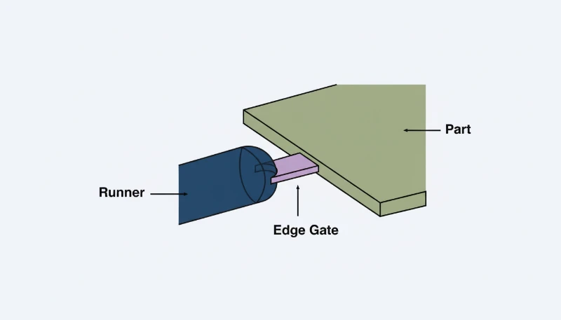
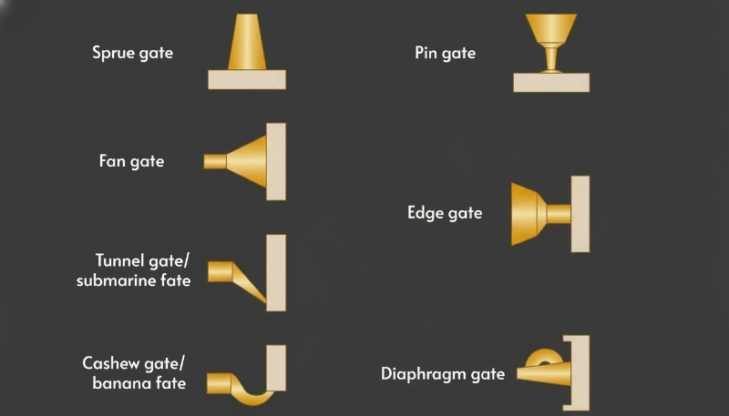
1. Edge Gate
- 説明 A rectangular gate located on the parting line of the mold.
- 長所だ: simple design; low cost; easy to machine; good for filling large flat parts.
- 短所だ: Leaves a visible mark on the edge; requires manual trimming (labor intensive).
- 最適: Hidden internal components, structural parts.
2. Pin (Pin-Point) Gate
- 説明 A very small circular gate, typically used in three-plate molds3, feeding directly into the cavity surface.
- 長所だ: Minimal vestige (easy to break off); places gate near the center of the part.
- 短所だ: Requires complex three-plate mold (higher cost); high shear rate.
- 最適: Round parts (gears, caps), cosmetic covers.
3. Submarine (Tunnel) Gate
- 説明 An angled tunnel machined below the parting line that shears off automatically upon ejection.
- 長所だ: Submarine gate design allows for automatic degating; moves the gate mark away from the visible parting line.
- 短所だ: Difficult to machine; potential for shear burn; gate can flake if not designed correctly.
- 最適: High-volume small parts requiring no manual trimming.
4. Direct Sprue Gate
- 説明 The nozzle feeds directly into the part without a runner system.
- 長所だ: Minimum pressure loss; low tooling cost (single cavity).
- 短所だ: Large gate mark requires machining to remove; high residual stress near the gate.
- 最適: Large, single-cavity parts (e.g., buckets, trash cans).
A: その
| ゲートタイプ | Vestige Visibility | Trimming Method | 金型費用 | Shear Stress |
|---|---|---|---|---|
| Edge | High (On Edge) | Manual / Cutter | 低い | Low-Medium |
| Pin | Low (Small Dot) | Auto (Break-off) | High (3-Plate) | 高い |
| Submarine | Low (Hidden) | Auto (Shear) | ミディアム | 高い |
| スプルー | 非常に高い | 機械加工 | 低い | 低い |
How Does Gate Location Affect Defects?
The position of the gate creates the flow front pattern. Incorrect placement leads to predictable defects.
Preventing Gate Blush
Gate blush defects appear as cloudy or hazy patches near the gate.
- 原因がある: excessive shear stress or jetting (material shooting across the cavity rather than flowing).
- 解決策 Position the gate so the flow hits a wall or pin immediately (impingement), or use a fan gate to spread the flow velocity.
Controlling Weld Lines
Weld lines (knit lines) form where two flow fronts meet.
- Impact: These areas are structurally weaker and visually distinct.
- Strategy: Position the gate so weld lines form in non-critical areas. For a ring-shaped part, a single gate creates a weld line opposite the gate. Using a diaphragm gate can eliminate weld lines4 entirely.
What Is the Step-by-Step Process for Selecting Gate Location?
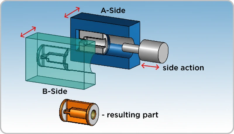
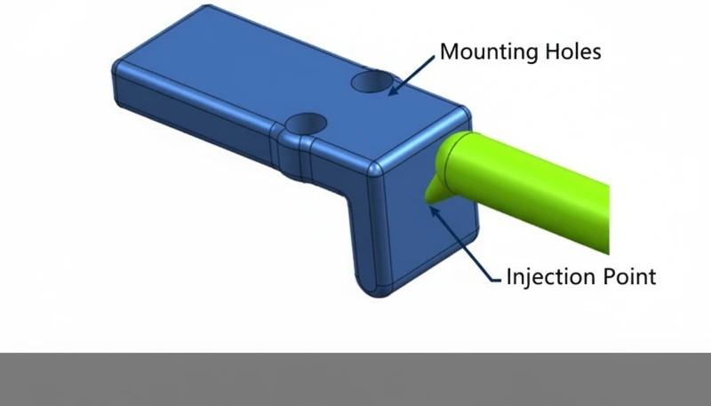
- Identify Aesthetic Surfaces: Mark the "A-side" (cosmetic side) and ensure gates are placed on the "B-side" or hidden edges whenever possible.
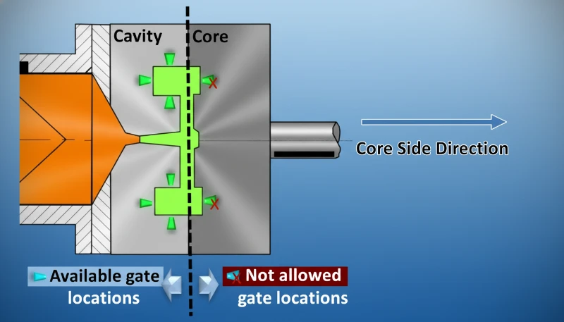
- Locate Thick Sections: Identify the heaviest wall sections. Gate here to ensure the material stays molten long enough to pack out the part.
- Analyze Flow Length: Ensure the L/t (Flow length to thickness ratio) is within limits for the chosen material. If the path is too long, multiple gates may be needed.
- Check for "Jetting": Avoid gating straight into an open cavity. Aim the gate at a core pin or wall to create laminar flow.
- Simulate: 用途 Moldflow® analysis5 to visualize filling patterns, air traps, and weld line locations before cutting steel.
Positioning the gate in the center of a round part ensures uniform radial flow.真
Center gating promotes even distribution of material and pressure, significantly reducing warping and improving concentricity in gears and caps.
Multiple gates always reduce the likelihood of defects in large parts.偽
While multiple gates reduce flow length, they create multiple weld lines where flow fronts meet. If not managed correctly, this can reduce structural integrity and aesthetics.

What Are the Practical Tips for Optimizing Gate Design?
- Start "Steel Safe": Always machine the gate slightly smaller than the calculated target. It is easy to remove metal to open the gate (make it larger), but welding metal back to make it smaller is expensive and difficult.
- Submarine Angles: について submarine gate design6, ensure the angle is typically between 30° and 45° to ensure clean shearing during ejection.
- Cashew Gates: For aesthetic parts where the gate must be hidden on the underside but cannot be a standard sub-gate, use a curved "cashew" or "banana" gate.
よくある質問(FAQ)
Q: What is the best gate type for hiding marks completely?
A: The 主要な洞察:射出成形におけるゲート位置 or the "cashew" gate is best. They allow the gate to be placed on a non-visible surface or the underside of the part and shear off automatically, leaving a very clean finish.
Q: Why is direct sprue gating not used for precision parts?
A: Direct sprue gating leaves a large vestige that must be machined off, which adds cost. More importantly, it often introduces high residual stress at the injection point, which can cause warping or environmental stress cracking in sensitive materials.
Q: Can I move the gate after the mold is built?
A: It is extremely difficult and expensive. Moving a gate usually involves welding the old gate shut (which can leave polish marks) and EDM (Electrical Discharge Machining) a new gate. It often requires creating a new insert.
Q: How does gate size affect the process?
A: A gate that is too small causes high shear (burning the material) and limits packing pressure (causing sink marks). A gate that is too large increases the cycle time (takes longer to freeze) and leaves a larger vestige.
Q: What causes "jetting" at the gate?
A: Jetting occurs when the molten plastic shoots through the gate into an open cavity without touching the walls, cooling into a snake-like strand before the rest of the mold fills. This is fixed by aiming the gate at a wall or increasing the gate size.
概要
について role of gate location extends far beyond simply filling the mold. It is a strategic decision that defines the structural integrity, cosmetic quality, and production efficiency of the part. By understanding the trade-offs between injection molding gate types—from the economical edge gate to the automated submarine gate—and adhering to design principles like gating into thick sections, manufacturers can avoid costly defects like gate blush and warpage. Proper simulation and planning during the design phase are the keys to a successful mold launch.
-
Understanding gate location is crucial for optimizing part quality and minimizing defects in injection molding. ↩
-
Learn about the causes of sink marks and effective strategies to reduce their occurrence. ↩
-
Discover the functionality of three-plate molds and their application in creating complex parts. ↩
-
Understand the impact of weld lines on structural integrity and aesthetics in molded parts. ↩
-
Explore how Moldflow® analysis helps visualize filling patterns and optimize gate placement. ↩
-
Explore the design principles for submarine gates to ensure optimal performance and aesthetics. ↩


