 Skip to content

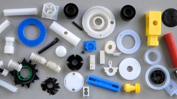
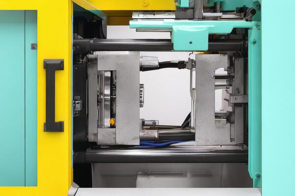
Introduction: Most plastic stuff is made by injection molding. It’s a great way to make lots of things fast and cheap. But you have to be careful. If you don’t, your parts won’t fit together when you try to put them together.

That’s bad because the molds cost a lot of money. This article will show you how to make sure your parts fit together and are good quality.
What are Injection Molding Tolerances?
Stuff shrinks. It’s a fact of life. And it’s not always the same. So you have to set a range of acceptable shrinkage so the part will work.
These ranges are called tolerances. They’re really important for big parts and parts that are made of more than one part. If the parts don’t fit together because they’re not within the tolerances, the part won’t work. And you won’t be happy.

Injection molds are CNC machined with tolerances of ±.005 inches. Injection molding tight tolerances refer to variations of ±.002 inches. Very tight tolerances refer to ±.001 inches. Parts with normal tolerances are priced lower than parts with tighter tolerances.
Therefore, determining the optimal tolerances for injection molded parts is important to produce high-quality parts in an affordable manner.
Why are Injection Molding Tolerances So Important?
It’s important to specify injection molding tolerance correctly so that the final part will fit together when it’s assembled.

You can control injection molding tolerances by using good design and manufacturing principles, choosing the right material, designing the tool correctly, and controlling the process.
When you make parts, they’re not all going to be exactly the same. You have to define how much variation is acceptable so that the parts will work the way you want them to. This becomes more important when you start putting parts together.
For example, if you have two flat parts that have to be bolted together, the holes in each part have to be in the right place. The holes in one part have to be in the right place relative to the holes in the other part.

It sounds simple, but when you start putting a bunch of parts together, one part can screw up the whole thing.
You can use tolerance stacking and statistical analysis to figure out how to make injection molded parts that will work together.
What are the Factors That Affect Injection Molding Tolerances?
Part Design
One of the most important ways to limit warpage, excessive shrinkage, and part misalignment is to use DFM principles when designing your parts.

This is best achieved by working with your injection molding project early in the design process to prevent costly redesigns later in the design phase.
Wall Thickness
Parts with variable wall thickness can experience uneven shrinkage. When thick areas can’t be avoided, coring must be used to keep the wall thickness uniform.
Uneven wall thickness can cause part deformation, which can affect tolerances and assembly.
Thicker walls aren’t always the best choice for added strength; where possible, it’s better to use ribs and gussets to improve part strength.
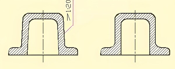
Draft Angle
Draft angle is super important to make sure your part comes out of the mold easily.
If it’s not right, your part can get stuck when you try to get it out, and it can scrape and warp your part. Draft angle can be anywhere from 0.5° to 3°, depending on your part design and surface finish.
Boss Features
Bosses are often used to accommodate fasteners when assembling multiple plastic parts. If the bosses are too thick, they may leave indentations on the part.
If they are not connected to the sidewalls by ribs, they may deform significantly. This will make assembly of these parts almost impossible.
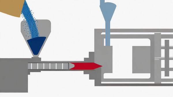
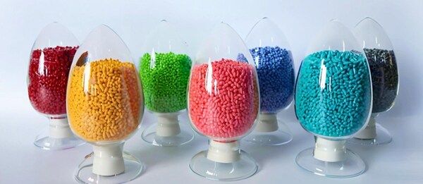
Material Selection
You can make injection molded plastics from a bunch of different resins. The one you pick depends on what you’re making.

Each resin shrinks a different amount. When you design the mold, you have to account for this shrinkage. You usually make the mold bigger by the percentage the material shrinks.
If you’re making a multi-material assembly, you have to design for different shrinkage rates.
If you don’t design the tolerances right, you can end up with parts that don’t fit together. That’s a big mistake in injection molding.

Tolerances for injection molding are mainly determined by material shrinkage and part geometry. You need to finalize material selection before you design and build the tool. The tool design depends a lot on the material you choose.
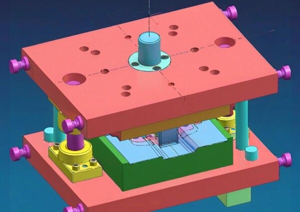
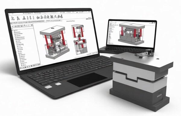
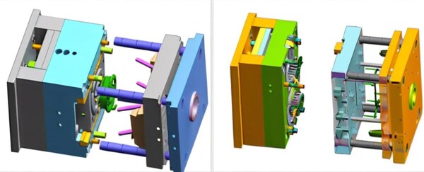
Tool Design
Once you’ve selected your material, you’ll typically oversize your tool to account for the shrinkage that’s going to happen to that material.
But shrinkage doesn’t happen consistently in all dimensions. For example, thicker parts cool at different rates than thinner parts.

So, if you have a complex part with a mixture of thin and thick walls, you’re going to have variable cooling rates.
And that warpage or sinking can seriously affect your injection molding tolerances and fit. So, to limit these effects, tool manufacturers consider the following when they’re designing mold features.
Tool Cooling: Cooling is important. Bad cooling will make the part bad. Good cooling will make the part good. Put the cooling in the right place.

Tool Tolerance
If a tool is out of tolerance, every part that is molded with that tool will have that error added to any error caused by shrinkage.
However, in CNC machining, tool tolerances are typically tightly controlled and monitored, so an out-of-tolerance tool is rarely the reason a part is out of tolerance.
Additionally, these tools are typically “steel safe.” This means that when a tool is made, critical dimensions or features can be adjusted with additional milling.

If the finished dimensions of certain parts are out of tolerance, the additional material allows the tool to be fine-tuned through machining.
For example, a close tolerance hole feature on a part may have a tool that is designed with a core pin that is on the wider side of the tolerance.
If the hole needs to be adjusted, it will be machined thinner to make the hole thinner.

Ejector Position
The ejector pushes the mold out of the mold as it opens. This needs to be done as quickly as possible to minimize cycle time.

If the ejector is placed in a non-ideal position, it can damage the part. Some materials are not completely rigid when they leave the tool. Uneven ejection can cause severe warpage and dimensional inconsistencies.
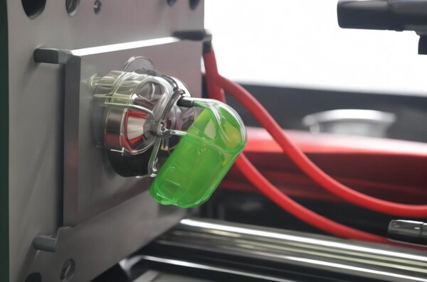
Gate Location
The gate is where the resin goes into the tool. If you put it in the wrong place, it will look bad.
Also, if you don’t fill the mold evenly, you’ll get warpage and shrinkage. Sometimes you need more than one gate to fill the mold evenly and avoid these problems.
Process Control
Even if you do all the upfront design work and material considerations to optimize a part for injection molding tolerances, it’s possible that the part will be out of tolerance when the first samples are delivered.
Once you’ve combined all of the above methods, the next step to improve tolerance compliance is to adjust the process.
Controlling temperature, pressure, and dwell time are some of the most common ways to improve part quality.
Once you’ve determined the ideal set of conditions, the mold can create consistent parts with very little dimensional variation from part to part.
When you’re dealing with complex, multi-feature parts, it can be a good idea to put pressure and temperature sensors in the tool to measure these parameters during the manufacturing process for real-time feedback and process control.

Keeping pressure and temperature in the tool all the time can help you hold consistent tolerances.
When you’re dealing with complex, multi-feature parts, it can be a good idea to put pressure and temperature sensors in the tool to measure these parameters during the manufacturing process for real-time feedback and process control.
Keeping pressure and temperature in the tool all the time can help you hold consistent tolerances.
How to Optimizing Injection Molding Tolerances?
Designing Parts for Manufacturability
To avoid expensive and time-consuming redesigns later on, it’s important to predict tolerance problems early in the design process.
To minimize the risk of warping and misalignment, designers should follow design for manufacturability (DFM) guidelines. DFM means designing parts with a specific manufacturing process in mind.
When you’re designing a part for manufacturing, you need to think about how it’s going to be made. That means you need to consider things like how thick the walls should be, how much you should angle the sides, and what kind of design features you should include, like bosses.
One of the most important things to think about is how thick the walls should be. If the walls aren’t the same thickness all the way around, the part will shrink unevenly when it cools down.
That can make the part warp, and if it warps, it won’t be able to hold tight tolerances. Sometimes, it’s better to add support ribs to make the part stronger instead of making the walls thicker.
Draft angles are important for making sure parts come out of the mold without warping or scratching. The right angle will depend on the part and the finish you want, but 1.5-2 degrees of draft is usually the least you should use for most injection molded parts.

Bosses are raised part features that are often used to hold multiple plastic parts together during assembly. If the boss is designed too thick, it can cause sink marks on the surface of the part.
In addition, if the bosses are not connected to the side walls of the part (usually done through support ribs), they can easily deform or warp, which can seriously hinder the ability of the component to be fastened together.

Size matters
The bigger the part or product you’re making, the more important tolerances become. In plastic injection molding, a bigger part can warp or shrink. So, size matters.

Boss
Bosses are a big deal in product design. They’re used to hold parts together when you’re putting them together.There are some things you need to think about when you’re designing bosses. One is that the walls of the boss can’t be too thick.
If you make the boss too thick, you’ll get voids and sink marks. That’ll make it take longer to make the part and it’ll crack when you put it together.Also, you should core the bosses (i.e., connect them to the nearest side wall). Doing so gives you more load distribution on the part and makes the part cooler and the material flow better.
Choosing the ideal material for your application
Material selection is just as important as part design when it comes to injection molding tolerances. There are many different plastics that can be used in the scientific injection molding process. Different materials have different shrinkage rates.

This must be taken into account when selecting injection molding material and designing molds. If a part is made up of more than one material, the different shrinkage rates must be taken into account to ensure that the parts fit together as intended.

Therefore, it is important to have a good understanding of the different injection molding materials to ensure consistent injection molding tolerances.
Injection molding works with lots of different kinds of plastic – and you can make them even better by adding stuff to them. You can also make them stronger or more stable.
Being able to choose from so many different materials is great for product teams because they can make the materials and performance qualities they want for their product even better.

Different resins shrink at different rates, so you need to consider this when choosing a material and designing the mold.
If you’re assembling parts made from different materials, you need to account for the different shrink rates to make sure the parts fit together like they’re supposed to.
Knowing the properties of the resin you’re using is the key to getting consistent tolerances in plastic injection molding.
When you’re picking materials, use these factors to help you choose:
Plastic composition
Amorphous plastics (like ABS) shrink less than semi-crystalline plastics (like polyethylene) because they’re less tightly packed.
Molecular weight
High molecular weight resins have high viscosity and high pressure drop, which can increase shrinkage.
Additives
Adding fillers with low thermal expansion will reduce shrinkage.Different resins have different shrinkage rates. Therefore, you must account for this in material selection and injection mold design to reduce cosmetic defects such as warpage, sag, cracking and distortion, which can affect the tolerances of the molded part.
Keep Tooling Considerations in Mind
Since mold tools are usually made a little bigger to allow for material shrinkage, the first thing you need to know is what material you’re going to use.Good tool design is critical to making sure parts cool properly and meet tight injection molding tolerances.

Mold tools need to provide consistent, repeatable heating and cooling between shots—otherwise it will be difficult to maintain tight tolerances, which is especially important as part (and tool) complexity increases.
Poor or inconsistent cooling can lead to significant deviations from tolerance requirements. By monitoring injection pressure, resin viscosity, and fill time, engineers can track and adjust production variables to ensure proper pressure, heating, and cooling during the injection process.
To make sure the resin flows into the mold evenly and to prevent shrinkage and warping, you need to figure out where to put the gate (the hole where the resin goes in).

If you’re making a complicated injection molded part, you might need more than one gate to make sure the resin fills the mold evenly and cools down right. You also have to think about where to put the ejector pins.
They can mess up the size of the part because some materials aren’t totally stiff when you take them out of the mold (usually to make the cycle time shorter).
You have to put the pins in the right place so the part doesn’t warp and the surface doesn’t get messed up.
While tolerances on the tool itself are typically very tightly controlled (some level of refinement can be done if a CNC machined mold is producing a component that is not within acceptable tolerances), this is another important consideration that the product team should carefully examine.
When you’re picking the right material, mold designers will offer to oversize the mold to account for material shrinkage.
Different materials have different shrinkage rates because of uneven thickness. To reduce this, you should consider the following points when designing the mold.

Tool Cooling
Cooling is a big deal in scientific molding . It’s what makes the difference between a good part and a bad part. Cooling is the process of cooling down the plastic after it’s been heated and before it’s ejected.
Cooling has to be even. If it’s not, you’ll get shrinkage, sink marks, ejection problems, warpage, and all kinds of other problems. These problems can affect the way the part looks, the way it fits, and the way it works.
To get the cooling right, you need to put the cooling channels in the right places in the mold. You may also need to keep an eye on things like injection pressure, resin thickness, and how long it takes to fill the mold.

Tooling Tolerances
Injection molds are typically made using CNC machining, which allows for tight tolerances to be achieved, thus maintaining accuracy throughout the heating and cooling cycles of the process.

Tolerances will make sure the part cools right without messing up the accuracy. It’s not common because of CNC machining, but if you don’t control tolerances when you make molds, you can get some serious defects like warping, shrinkage, and sinking.
Ejector Pin Location
The ejector pin is a feature in the injection mold that pushes the final product out of the mold. The pin has different shapes (preferably flat) through which a certain force is applied to push the product out.
Therefore, when it is placed in the wrong position, it may cause unnecessary indentations on the finished product.
In addition, in non-rigid materials or materials that cool unevenly, ejector pins can cause unfinished products to crack, resulting in some cosmetic defects and physical anomalies.
Gate Location
The gate is where the plastic goes into the mold. When you decide where to put the gate, you should think about: Put the gate where the plastic is the thickest: This will make the part stronger and look better.

Put the gate where the plastic is the thickest: This will make the part stronger and look better. Put the gate where the plastic is the thickest: This will make the part stronger and look better. Don’t put the gate where there are things in the way like pins and other parts.
Don’t put the gate where it will make the runner look bad or make the part look bad. The gate has to be in the right place because if it’s in the wrong place, it will make the part look bad and not work right.
Implement Repeatable Process Control
Process control is how manufacturers calibrate variables that can affect part quality. These variables are an integral part of every manufacturing process and their calibration helps reduce deviations. Common variables are temperature, pressure, and holding time. A few ways to achieve this include:

You can embed temperature and pressure sensors in the mold to measure the mold environment and provide real-time feedback and repeatable process control.
Resins have a high coefficient of thermal expansion and will cause dimensional changes due to temperature changes.
Therefore, when the part is processed at a constant temperature. The manufacturing process involves a large number of variables that affect the viability and quality of a part, and process control is a means of calibrating these variables to minimize deviations.

Pressure and temperature sensors in mold tools are important for good process control because they give you real-time feedback on these parameters.
This lets you make quick adjustments when you see something going wrong. Once you have these variables under control and can repeat them, the mold tool will make parts with tight tolerances and little variation.
Plastic resins usually have a higher coefficient of thermal expansion, which means they are more likely to change dimensions when the temperature changes.

So, parts with tighter tolerances often need to be measured at the same temperature to make sure they stay the same size and work right.
Achievable Injection Molding Tolerances
To get real injection molding tolerances, you can put some doable plastic injection molding tolerances into your plastic mold design. Here are the main plastics that are usually used in plastic injection molding:
Dimensional Tolerances +/- Mm
Accuracy is a tough thing to maintain. That’s why designers use the (+/-) symbol to show the range of measurements.

Every material has a different tolerance range as the size gets bigger. The table above shows the dimensional tolerances of the main plastics for injection molding.
Straightness/Flatness Tolerance
Warp happens because the plastic shrinks at different rates in the direction of flow and across the direction of flow. It can happen because of different wall thicknesses, which shrink at different rates. You can minimize warp by adjusting the mold design, finding a better gate location, and controlling the process.
However, you may have to have a practical tolerance on the plastic side because it’s hard to get 100% of the warp out.
Hole Diameter Tolerance +/- Mm
The bigger the hole, the more tolerance you need to think about. The picture above shows you the tolerances for different hole sizes.
Blind Hole Depth Tolerance +/- Mm
Blind holes are holes drilled in the workpiece using an insert core without going all the way through. They are pinned and fixed at one end, which makes them more likely to deform under strong melt flow forces. The figure above shows the different tolerances you can use.
Concentricity/Ovality Tolerance +/- Mm
This is where you determine the wall thickness (the difference between the OD and the ID). The chart above shows the different tolerances and the cost difference to achieve that tolerance.
Conclusion
There’s always some variation in injection molding, so there has to be an allowable range of deviations to allow the part to function properly after assembly.

That’s why injection molding tolerances are so important when you’re assembling products with multiple injection molded parts. Additionally, injection molding design follows manufacturability principles to optimize wall thickness, draft angles, and boss features to ensure parts maintain tight tolerances during production and assembly.
When you control and optimize injection molding tolerances, you can figure out the allowable range of deviations that will help your product function at its best.

There are a lot of ways to do this, but they all depend on DfM, material selection, and process control. This article helps you simplify some of the most useful ways to do it for your project.


