 Skip to content

Gas Assisted injection molding is a process that uses gas to help push plastic material into the mold. This makes the process faster, more efficient, and results in a higher quality product.
Gas-Assisted Injection Molding (GRIM) is a new type of injection molding process, which has been widely used abroad in recent years and is increasingly used in China.
Gas-assisted injection molding is a process that uses pressurized gas to help injection molded parts cool faster and cure more quickly.
Gas assist molding is a low-pressure plastic injection molding process where pressurized nitrogen gas is injected into the mold, pushing the molten plastic into the mold extremities, while hollowing out thicker sections in the part.
This blog post will discuss what gas-assisted injection molding is and how it works!

Principle of Gas-Assisted Injection Molding
The principle is to use relatively low-pressure inert gas (nitrogen is commonly used because of its low cost and safety, and also the role of coolant, with a pressure of 0.5 to 300 MPa) to replace part of the resin in the cavity of the traditional molding process to maintain pressure, to achieve better molding performance of the product.

Advantages of Gas Assist Injection Molding
Gas-assisted injection molding overcomes the limitations of traditional plastic injection molding and foam molding and has the following advantages:
Good performance of parts
(1) Eliminate pores and depressions by reasonably opening gas channels in the reinforcement bars and tabs set up at the joints of different wall thicknesses of the parts and introducing gas after the injection of the underside material.
It compensates for the shrinkage of the melt during the cooling process and avoids the generation of pores and depressions.
This process to consider is its ability to pack out thick geometry that would result in sink marks with a traditional molding process.

(2) Reduce internal stress and warpage deformation During the cooling process of the part, a continuous gas channel is formed from the gas nozzle to the end of the material flow without pressure loss, and the air pressure is consistent everywhere, thus reducing residual stress and preventing warpage deformation of the part.
(3) Increase the strength of the part The design of the hollow reinforcement and tabs on the part makes the strength-to-weight ratio higher than that of similar solid parts by about 5, and the moment of inertia of the part increases substantially, thus increasing the strength of the part.
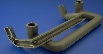
(4)To improve the flexibility of the design gas-assisted injection can be used to form products with uneven wall thickness, so that the original must be divided into several parts of separate molding products to achieve a single molding, to facilitate the assembly of parts.
For example, a foreign company originally produced dozens of metal parts as the main body, the shape of complex car door panels, through the GAI M technology and the use of plastic alloy materials to achieve a single molding.
Low cost
(1) Save raw materials by gas-assisted injection molding in the thicker parts of the product to form a cavity, which can reduce the weight of the finished product by up to 10% to 50%
(2) Reduce equipment costs gas-assisted injection requires less injection pressure and clamping force than ordinary injection molding (25% to 50% savings) while saving energy by up to 30%.
(3) Relatively shorter molding cycle time due to the removal of thicker parts of the core material, reducing the cooling time by up to 50%.
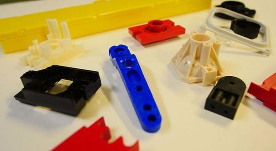
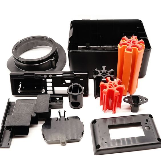
Based on these advantages, gas-assisted injection is suitable for molding large flat products such as tabletops, doors, boards, etc.; large cabinets such as household appliance housings, TV housings, office machinery housings, etc.; structural components such as bases, automotive instrument panels, bumpers, automotive headlight covers, and other automotive interior and exterior parts.

Selection of materials for gas-assisted injection molding
In theory, all thermoplastics that can be used in conventional injection molding methods are suitable for gas-assisted injection molding, including some filled resins and reinforced plastics.
Some plastics with very good fluidity and are difficult to fill, such as thermoplastic polyurethane, can be difficult to mold; resins with high viscosity require high gas pressure and are technically challenging, and glass fiber reinforcement materials can be abrasive to equipment.
In the gas-assisted molding process, as the molding wall thickness and surface defects of the parts are largely determined by the performance of the raw materials, changing the process parameters does not have a great impact on them, so the choice of molding raw materials is extremely important.

Materials Used in Gas Assist Molding as with structural foam, almost any thermoplastic material can be used in a gas-assist application including • Polycarbonate • Polyphenylene Oxide – PPO (Noryl) • Polybutylene terephthalate – PBT (Valox) • Acrylonitrile Butadiene Styrene – ABS.
PA (polyamide) and PBT (polybutylene terephthalate) have unique crystalline stability and are particularly suitable for gas-assisted injection molding;
PA6, PA66, and PP are also often used for gas-assisted molding; for some partially crystalline resins, the inner side of the molding near the air channel has no obvious amorphous boundary layer due to the relatively slow cooling rate, but the outer side will produce an amorphous boundary layer due to the rapid cooling of the mold wall, which affects the quality of the product.
For glass fiber reinforced plastics, a slight molecular orientation will be produced at the mold wall, and the maximum molding high strength parts can be selected from resins with a high elastic modulus at a certain distance under the mold wall (about 1mm from the outer surface of the product) along the direction of material flow, and suitable resin materials should be selected according to the requirements of the parts and specific molding conditions in the actual production process.

Gas channel design in gas-assisted injection molded parts
Gas channel design is one of the most critical design factors in gas-assisted molding technology, which not only affects the rigidity of the product but also its processing behavior. Since it pre-defines the flow state of the gas, it also affects the flow of the melt during the initial injection stage, and a reasonable gas channel selection is essential for molding higher quality products.
Geometry of common gas channels
For large plate parts with reinforcement, the thickness of the substrate is generally taken as 3-6 mm for gas-assisted injection molding, which can be reduced to 1.5-2.5 mm for parts with a shorter gas flow distance or smaller sizes.
The wall thickness of the reinforcement can reach 100%-125% of the wall thickness of the part with which it is connected without creating a depression.
The geometry of the gas channel should be symmetrical or unidirectional concerning the gate, the gas channel must be continuous and the volume should be less than 10% of the whole part volume.
Analysis of the strength of the part
The traditional parts with reinforcement are often dented, warped and deformed, etc. The use of gas-assisted injection molding for reinforced parts with various cross-sectional geometries not only ensures the strength of the products but also overcomes the shortcomings of traditional injection molding.
Usually, under the same substrate thickness, the strength of the part with hollow wide T-shaped reinforcement is higher than that of the part with hollow narrow T-shaped reinforcement, which is higher than that of the part with hollow semicircular reinforcement of the same cross-section.
The strength of the product varies greatly with the size of the force and its form, although the use of reinforcement can increase the stiffness of the product, if the local concentration of stress is applied to it, it will greatly weaken the strength of the product.
Size of gas channel
The size design of the gas channel is closely related to the flow direction of the filling gas, which always flows in the direction of least resistance in the flow channel.
Stable Newtonian fluid through a circular tube of diameter D, the pressure drop formula is ΔP = 32μVL/D, where μ is the fluid viscosity, V is the average flow rate, L is the length of the fluid section, D is the diameter of the tube, because the gas full viscosity is very small, less than 0.1% of the resin and the pressure drop in the length direction can be ignored, and thus only the resistance generated by the resin pressure drop needs to be considered.
Pseudoplastic fluid flow in a circular tube pressure drop formula and Newtonian fluid form is similar, so the use of the above formula without considering the actual fluid and gas conditions, compared based on the gas near the pouring point of different directions of the pressure drop ΔP (i.e., compare the size of each section of L and D), can qualitatively solve the problem of gas Zhu filling direction ΔP small direction that is the preferred direction of gas flow.
Changing the size of the flow channel directly leads to the change of the pressure drop in different directions, which changes the flow direction of the gas and affects the quality of the molded part.

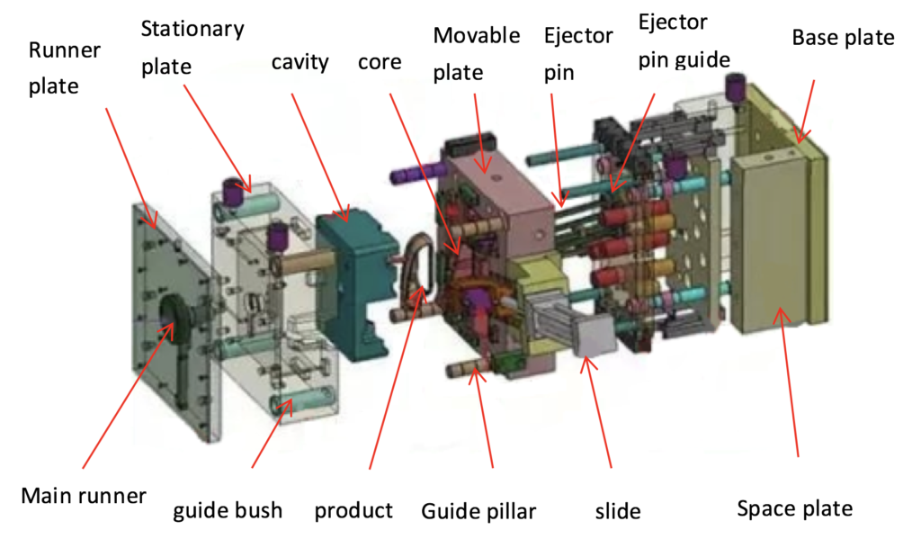
Gas Assist Injection Molding Mold Design
Since internal gas-assist injection molding uses relatively low injection pressure and clamping force, the mold can be made of zinc-based alloy, forged aluminum, and other light alloy materials, in addition to the general mold steel.
The mold design of the gas-assisted injection molding process is similar to that of normal plastic injection molding. The defects caused by the design of the mold and part structure cannot be compensated by adjusting the parameters of the molding process, but the design of the mold and part structure should be modified in time.
The design principles required in general plastic injection molding are still applicable in the gas-assisted injection molding process, and the following are the main considerations for different parts of the design:
(1) Avoid the phenomenon of injection Although there is a trend of gas injection toward thin-walled products and the production of special-shaped bends, traditional gas injection is still used to produce large cavity volume parts, the material flow through the gate is subject to high shear stress, prone to melt rupture phenomena such as injection and creep.
The design can appropriately increase the size of the inlet gate and set the gate at the thin products to improve the situation.
(2) Cavity design due to gas injection in the amount of underfill, gas injection pressure, time, and other parameters difficult to control consistent, so gas injection generally requires a mold cavity, especially when the product quality requirements should be high.
In actual production, there are examples of four cavities in one mold, and when using a multi-cavity design, it is required to use the balanced pouring system arrangement.

(3) Gate design generally uses only one gate, and its position should be set to ensure that the melt of the under-injected part is evenly filled with the mould cavity and to avoid jetting.
If the gas needle is installed in the injector nozzle and the pouring system, the gate size must be large enough to prevent the melt from condensing here before gas injection.
One of the most common problems in the gas-assisted injection is that the gas penetrates through the intended gas channel into the micro thin layer of the part, forming finger-like or leaf-like gas fingering on the surface, even a few such “fingerprints” can be fatal to the product and should be avoided at all costs.
Research shows that the main reason for the formation of such defects is due to the inappropriate gate size and gas delay time settings, and these two factors often interact, for example, when using a smaller shallow mouth and a shorter delay time, it is very easy to produce such adverse consequences, not only affect the appearance of the product quality and greatly reduce the strength of the part.
Generally, we can use the method of shortening the length of the gas channel, increasing the size of the inlet gate, and reasonably controlling the gas pressure to avoid this unfavorable situation.
(4) The geometry of the runner should be symmetrical or unidirectional concerning the gate, and the direction of gas flow and the direction of molten resin flow must be the same.
(5) The overflow space to regulate the flow balance should be designed in the mold to get the ideal hollow channel.

Development prospects of gas-assisted injection molding
In recent years, gas assist technology has been widely used in household appliances, automobiles, gas-assist office supplies, and other industries, and it is developing in the direction of improving the dimensional stability of products, manufacturing thin-walled products with excellent surface properties, producing special-shaped pipes, replacing metal parts in the automotive industry, etc. It is believed that gas injection technology will still play an important role in future industrial production.


