Introduction: Injection molding is a manufacturing process that is used to make a wide range of plastic parts. You can use it to make small things like the caps on bottles of medicine, or big things like the body panels on cars.

Injection molding machines use injection molding materials to produce a variety of injection molded parts . But What is injection molding design like ? how do you design a mold? That’s what this article is about.
Analysis And Digestion of 2D And 3D Drawings of Products
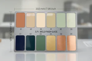
When you analyze and digest 2D and 3D drawings of products, you need to look at the following things: the shape of the injection molded part. The size, tolerance, and design requirements of the product. The technical requirements (also known as specifications) of the product.

The name, shrinkage, and color of the plastic used in the product. The surface requirements of the product. You need to check if the product design meets the expected functional requirements, such as strength, durability, etc.
You need to analyze the environmental performance of the product, including whether the material can be recycled and what the environmental impact is when the product is used. You need to evaluate whether the material selected is suitable for the product’s use environment and function.

Determination of Injection Type
When you choose an injection molding machine, you need to consider the plasticizing rate, injection volume, clamping force, effective area for installing the mold, ejection form, and fixed length.

That’s why some customers send the information of the injection molding machine together with the RFQ for your reference.
Determination And Arrangement of Mold Cavity Number
The mold cavity number is the number of mold cavities with the same structure in the mold, usually 2, 4, 8, 16, 24, etc. Different cavity numbers should be selected based on different production requirements.

Selection Based on Product Requirements
You can choose the number of mold cavities according to the specific product you want to make. You need to consider many factors, such as the size of the product, the demand for the product, the surface finish of the product, and the cost of the product.

Large products usually require fewer mold cavities. Because fewer cavities mean more space, it is suitable for the production of large parts. For small parts, such as precision parts or non-precision parts, you can choose more mold cavities to improve production efficiency.
Considering Cost
Another thing to think about is cost. The cost of making a mold is usually high, but as you make more molds, the cost of each mold usually goes down. This is because you’re making fewer parts, so you need fewer molds.

So if you’re making a lot of parts, you might want to think about making more molds to make more parts at once and save money.
Balanced Production
Manufacturers need to consider production balance in addition to product demand and cost. Some production lines and machines require more downtime for maintenance and parts replacement than others.

However, if the number of machines is sufficient, the combination product may need to change the mold at any time, so production can be balanced by selecting molds with different numbers of cavities.
Production Target
The number of mold cavities should be determined based on the output of the required products. The production target is closely related to the number of mold cavities.

If the production target is mass production, the number of mold cavities should be as large as possible; if the production target is small batch production, the number of mold cavities should be relatively small.
Production Efficiency
The number of mold cavities is important for production efficiency. If the number of cavities is too small, you’ll make fewer products at once and be less efficient.

If the number of cavities is too large, the mold will move slower and you’ll be less efficient. So, when you decide how many cavities to use, you need to balance efficiency and output to make sure you’re as efficient as possible.
Determination of Parting Surface
Some injection molds have only one parting line, while others have multiple parting lines. The parting line for removing the plastic part after parting is called the main parting line, and the remaining parting lines are called auxiliary parting lines.

The position and shape of the parting line. It is a straight parting line; it is an inclined parting line; it is a stepped parting line; it is a curved parting line; it is a flap parting line.
Determining the parting surface is a more complex matter. The parting surface is influenced by the molding position of the plastic part in the injection mold, the design of the injection system, the structural processability and special properties of the plastic part, the position and shape of the insert, as well as the ejection method, the manufacture of the injection mold, the exhaust, the operation process and other factors.

Therefore, when selecting the parting surface, a comprehensive analysis and comparison should be made to select a more reasonable solution from several solutions. When selecting the parting surface, the following basic principles should generally be followed:
The Parting Surface Should be Selected at the Contour of the Plastic Part
Once you’ve figured out where the plastic part is going to come apart, you need to put the parting line where the plastic part is the biggest in cross section. If you don’t do that, you won’t be able to get the plastic part out of the mold.

Determine a Favorable Mold Retention Method
To make it easier to remove the plastic part from the mold: When choosing where to split the mold, try to keep the plastic part on the side that moves when the mold opens. This way, you can put the ejector mechanism on the moving side of the mold.
Otherwise, you’ll have to put the ejector mechanism on the stationary side of the mold, which usually makes the whole mold more complicated. After the plastic part shrinks, it wraps around the stationary mold core. When you split the mold, the plastic part will stay on the stationary side.

This means you have to put the ejector mechanism on the stationary side of the mold, which makes the mold more complicated. If you split the mold, the plastic part will stay on the moving side.The ejection system of the injection machine and the ejection system of the injection mold can be used to eject the plastic part.
Sometimes, the selection of the parting surface can ensure that the plastic part remains on the moving mold side, but different positions will still affect the complexity of the injection mold structure and the difficulty of ejecting the plastic part.

Even though the plastic part stays on the moving mold after it separates, it’s hard to put in a good ejection mechanism when the hole spacing is small.
Even if it can be set, the required demolding force is large, which will increase the complexity of the injection mold structure and easily produce adverse consequences, such as warping and opening of the plastic part: because only a simple ejection plate is set on the movable mold as a demolding mechanism, it is more reasonable.

Ensure the Precision Requirements of Plasticity
If you need high precision or if you have a shape or a hole that needs to be coaxial, you should try to put the height dimension in the same half of the mold as the parting line so that it will be in the same half of the mold cavity.
If you have a part that has a high precision surface on it and you put the parting line through that surface, you may not be able to hold the shape and size because of the mold precision and you may have to scrap the part because it doesn’t meet the precision requirements.

If you have a double-gated part, you can mold one half of the part in the moving side of the mold and the other half of the part in the stationary side of the mold and you can hold the coaxiality of the part because of the way the two halves of the mold come together.
Meet the Appearance Quality Requirements of Plastic Parts
When choosing where to split the mold, you don’t want to mess up how the part looks. You also want to think about whether the flash that forms at the split line is easy to trim. Of course, you don’t want flash where it will show.

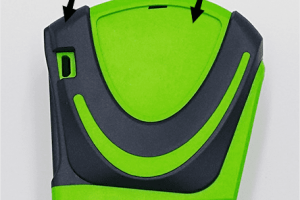
You don’t want flash at a rounded corner because it’s hard to trim and it messes up how the part looks. You don’t want flash because it messes up how the part looks. The part in the picture is likely to flash: even though you’re supposed to put a 2° to 3% draft on the outside, it doesn’t flash.
Convenient for Injection Mold Processing And Manufacturing
To make injection molds easier to process and manufacture, choose straight parting surfaces or parting surfaces that are easy to process. If you use a straight parting surface, the shape of the lower end of the plastic part is made on the push tube.

This push tube is difficult to process, and anti-rotation measures must be taken during assembly.At the same time, it will be damaged by the lateral force. If you use a stepped parting surface, it is convenient to process, and the core and type control processing are both difficult: if you use an inclined parting surface, it is easier to process.
Impact on the Molding Area
When designing the parting surface of an injection mold, the injection machine usually specifies the molding area and the rated clamping force allowed for the corresponding injection mold.

During the injection molding process, if the projected area of the plastic part on the parting surface of the mold exceeds the allowed molding area, the mold will expand and overflow. At this time, the clamping force required for injection molding will also exceed the rated clamping force.
Therefore, in order to reliably lock the mold and avoid mold expansion and overflow, the projected area of the plastic part on the parting surface of the mold should be minimized when selecting the parting surface.

If the projected area of the plastic part on the parting surface of the mold is large, the mold clamping reliability is poor; if the parting surface is used, the projected area of the plastic part on the parting surface of the mold is small, which ensures the mold clamping reliability.
It is Conducive to Improving the Exhaust Effect
The parting surface should be as close as possible to the inner wall surface of the cavity where the end of the plastic melt flow is located when the cavity is filled. Its exhaust effect is poor, and the structure is beneficial to the exhaust during the injection process. Therefore, the parting is reasonable.

The Impact on Lateral Core Pulling
When the plastic part needs to be pulled out sideways, in order to make it easy to put the side core in and make the core pulling mechanism work smoothly, when choosing the parting surface, the shallow side concave hole or the short side convex platform should be used as the core pulling direction,
And the deeper concave hole or the higher convex platform should be placed in the direction of opening and closing the mold, and the side core pulling mechanism should be set on the side of the moving mold as much as possible.

The above explains the general principles and some examples of selecting the parting surface. In actual design, it is impossible to meet all the above principles. One ship should grasp the main contradiction and determine a reasonable parting surface under this premise.
Determination of Mold Base And Selection of Standard Parts
Most of the time, customers will ask us which materials to use. But sometimes when we choose it ourselves, it is important to check the necessary strength and rigidity of the mold-related parts to check whether the selected mold frame is suitable, especially for large molds.

Design of Pouring System
The runner system, also called the runner system or pouring system, is the necessary passage for the molten plastic from the injection nozzle to the mold cavity. The runner system includes the main runner, the sub-runner, and the gate.
Main Runner
Also known as the main runner, sprue or vertical runner, this is the runner from the part where the injection nozzle contacts the main runner bushing of the mold to the sub-runner. This is the first part that the molten plastic resin flows through after entering the mold.

Sub-Runner
Also known as the sub-runner or secondary runner. According to the mold design, it can be further divided into the first sub-runner (First Runner) and the second sub-runner (Secondary Runner).

The runner is the transition area between the main runner and the gate, which can smoothly change the flow direction of the molten plastic; for multi-cavity molds, it also has the function of evenly distributing plastic to each cavity.
Gate
Also called the sprue, it’s the narrow channel between the runner and the cavity, and it’s also the shortest and thinnest part. Its function is to speed up the plastic by using the constricted flow surface.

The high shear rate can make the plastic flow well (due to the shear thinning characteristics of the plastic); the temperature rise effect of viscous heating also has the effect of increasing the material temperature and reducing the viscosity.
After molding, the gate is first solidified and sealed, which has the function of preventing the plastic from flowing back and preventing the cavity pressure from dropping too quickly, causing the molded product to shrink and sag.After molding, it is convenient to cut off to separate the runner system and the plastic part.
Cold Well
Also known as a cold well, its purpose is to store the colder plastic wave front in the initial stage of filling to prevent the cold material from directly entering the cavity, affecting the filling quality or blocking the gate.

The cold well is usually set at the end of the main channel. When the length of the branch channel is long, the cold well should also be opened at the end.
Basic Principles of Gating System Design
Consideration of Cavity Layout
Try to use a balanced layout. The cavity layout and gate opening should be symmetrical to prevent uneven force on the mold, which can cause eccentric load and overflow. The cavity layout should be as compact as possible to reduce the size of the mold.

Consideration of Flow Guidance
Can guide the molten plastic to fill the cavity without generating eddy currents, and can exhaust smoothly; Try to avoid the plastic melt from directly impacting the core and metal insert with a smaller diameter to prevent the core from displacement or deformation.
Consideration of Heat Loss And Pressure Drop
The smaller the heat loss and pressure drop, the better. The process should be short. The flow channel cross-sectional area should be large enough. Try to avoid flow channel bending and sudden changes in flow direction (changing direction with arc angle).

The surface roughness should be low during flow channel processing. Multi-point gating can reduce pressure drop and required injection pressure, but there will be suture line problems.
Consideration of Flow Balance
When you fill multi-cavity molds, you want to balance the runners and fill the plastic in each cavity at the same time as much as possible to make sure the molded parts in each cavity are the same quality.

you want to balance the sprues as much as possible. If you can’t balance the sprues naturally, you want to balance them artificially.
Consideration Of Waste
To reduce runner waste and recycling costs, decrease the runner volume (length or cross-sectional area) while maintaining smooth filling without affecting flow and pressure loss.

Consideration of Cold Material
Design proper cold slug wells (and overflow grooves) in the runner system to trap the colder plastic wave front during the early stages of filling, preventing the cold slug from going straight into the mold cavity and messing up the filling quality.
Consideration of Exhaust
The plastic should be guided smoothly into the mold cavity, and the air in the mold cavity should be able to escape smoothly to avoid encapsulation and burning.

Consideration of Molded Product Quality
Avoid short shots, flash, sink marks, weld lines, jetting, residual stress, warpage, core shift, and other problems; when the runner system flow is long or multiple gates are poured (Multiple Gating), prevent warpage of the finished product caused by unbalanced flow, insufficient pressure holding, or uneven shrinkage.

good product appearance, easy gate removal and trimming, and gate marks do not damage the appearance and application of the plastic part.
Design of the Ejection System
The ejection form of the product can be summarized into three categories: mechanical ejection, hydraulic ejection, and pneumatic ejection.

Design Principles of the Ejection System
The ejection system has many forms, which are related to the shape, structure, and plasticity of the product. Generally, there are ejector pins, ejector sleeves, push plates, ejector blocks, and air pressure composite ejectors.
The design principles are: when selecting the parting surface, try to keep the product on the side with the demolding mechanism. The balance of ejection force and position ensures that the product is not deformed or broken.

The ejector pin must be set at a place that does not affect the appearance and function of the product. Try to use standard parts for safety and reliability, which is conducive to manufacturing and replacement.
The ejection position should be set at a place with high resistance and should not be too close to the insert or core. For deep cavity molds like box-shaped ones, the side resistance is the largest, and the top and side ejection methods should be used to prevent product deformation and bursting.

When there are thin and deep reinforcing ribs, an ejector pin is generally set at the bottom. At the product inlet, avoid setting ejectors to prevent cracking. For thin products, set ejectors on the runner to bring the product out. The ejector and the ejector hole are generally clearance fits.
If the fit is too loose, it will easily produce burrs, and if it is too tight, it will easily get stuck. In order to facilitate processing and assembly, and reduce the friction surface, generally, a 10~15mm fit length is reserved on the movable mold, and the rest of the hole is expanded by 0.5~1.0mm to form an escape hole.

In order to prevent the ejector from rotating during production, it must be fixed on the ejector plate. There are various forms, which must be determined according to the size, shape and position of the ejector.
Design of Cooling System
The cooling system of injection molds is very important in mold design, and has a great impact on the molding cycle and product quality of the products.

In design practice, different customers have different requirements for cooling system design. Designers must first meet customer requirements, and then combine the mold size structure and the actual situation of the factory for comprehensive design.There are three types of cooling systems for injection molds: vertical cooling channels, inclined cooling channels, and water well partition cooling channels.

Vertical cooling channels are perpendicular to one of the mold’s outer surfaces, inclined cooling channels are not perpendicular to any of the mold’s outer surfaces, and water well partition cooling channels have a larger diameter water well than the other water pipes and have a partition in the middle to divert the flow.
To make sure your plastic parts cool evenly, you need a mold cooling system that’s designed to boost productivity and guarantee product quality. Here are some things to keep in mind when you’re designing your system:

The Number of Cooling Holes Should be as Large as Possible And the Size Should be as Large as Possible
The temperature of the surface of the cavity is closely related to the size and density of the cooling water holes. The diameter of the cooling water holes is large and the spacing between the holes is small, and the temperature of the surface of the cavity is uniform.
The Distance From the Cooling Water hole to the Cavity Surface Should be Appropriate
The distance from the hole wall to the cavity should be appropriate, generally greater than 10mm, and 12 to 15mm is commonly used. If it’s too close, the cavity surface temperature is uneven; if it’s too far, the thermal resistance is large, and the cooling efficiency is low.

When the uniform wall thickness of the plastic part , the distance between the cooling water holes and the cavity surface should be the same. When the wall thicknesses of the plastic part is different, the cooling water channel at the thick wall should be close to the cavity.
During the injection molding cycle, the hot tip gates design can ensure that the product has consistent wall thickness, thereby improving molding quality.
Water And Material are Parallel, And the Cooling at the Gate is Strengthened
When molding, the high-temperature plastic melt is filled into the cavity from the gate. The mold temperature near the gate is higher and the temperature at the end of the material flow is lower.

Set the cooling water inlet near the gate so that the overall flow direction of the cooling water is similar to the flow direction of the material in the cavity (water and material are parallel), and the cooling is relatively uniform.
The Temperature Difference Between the Inlet And Outlet Water Should Not Be Too Large
If the difference between the temperature of the water going in and the temperature of the water coming out is too big, the temperature of the mold will not be even.

To make the whole product cool at about the same speed, you need to set up the cooling water pipes right so that the difference between the temperature of the water going in and the temperature of the water coming out is as small as possible.
Selection of Mold Steel
The choice of materials for making molds (cavity, core) is mainly determined by the batch size and plastic category of the product.

P20 Steel
P20 steel is widely used in making big injection molds. It has strong wear resistance, good hardenability, and good toughness. It is suitable for making big, medium, and small molds and is widely used in cars, home appliances, and other fields.
NAK80 Steel
NAK80 steel is an advanced heat-resistant and wear-resistant plastic mold steel with excellent comprehensive performance.

It has high hardness, high toughness, high wear resistance, high corrosion resistance, and other characteristics. It is suitable for manufacturing high-quality and high-precision molds.
718 Steel
718 steel is a steel with excellent processability and excellent mechanical properties. It has high hardness, high tensile strength, and high toughness. It can manufacture various precision molds and is widely used in automobiles, electronics, medical, and other fields.

S136H Steel
S136H steel is a high-quality stainless steel. It has good thermal stability, good thermal fatigue performance, and is not easy to deform. It is suitable for making high-precision injection molds, optical lens molds, and so on.
Factors to Consider When Selecting Mold Steel
Material Hardness
Plastic molds need to be hard enough to ensure the service life and stability of the mold. Common mold steel materials include P20, 718, NAK80, etc., which have high hardness and wear resistance.

Material Toughness
Plastic molds will be subject to certain impact and extrusion forces during use, so they need to have a certain toughness to prevent the mold from breaking and damage. Common mold steel materials have high toughness, such as S136, H13, etc.
Material Corrosion Resistance
When we make plastic molds, we have to use a lot of chemicals. So, we need to use a kind of steel that is not easy to corrode, so that the mold will not be corroded and damaged. The common steel materials for mold making have good corrosion resistance. For example, 420 and 2316 are good.

Material Processing Performance
When it comes to making and fixing molds, you need steel that’s easy to work with. Some of the best steel for molds is easy to cut and heat treat, like 718 and NAK80.
Material Price
Price is also an important factor in selecting plastic mold steel. Different mold steel materials have different prices, so choose according to your actual situation.

Confirmation of Mold Drawings
Once the mold design drawings are done, they must be sent to the customer for approval. Only after the customer agrees can the mold be put into production.

When the customer has a big opinion and needs major changes, it must be redesigned and then handed over to the customer for approval until the customer is satisfied.
Exhaust System
The exhaust system of the injection molding press mold is mainly to remove the air and volatiles in the mold cavity to ensure the stability of the quality of the injection molded products and improve the production efficiency.

If there is too much residual air in the mold cavity or the exhaust is not smooth, it will cause defects such as bubbles, shrinkage holes, and burrs in the injection molded products, affecting the product quality and molding efficiency.
Tangential And Radial Exhaust Method
By incorporating tangential or radial exhaust grooves or holes into the mold design, you can achieve tangential and radial venting, which effectively reduces gas buildup in the mold.

Cylindrical Exhaust Method
The exhaust port is designed as a small cylinder so that the gas can diffuse around it to achieve the purpose of exhaust.
Breathable Exhaust Method
A bunch of little channels are put in the exhaust hole or exhaust groove so that the gas goes between the little channels, so it can breathe.

Angle Annular Exhaust Method
A circular angle exhaust groove is set. During the injection molding process, the air on the mold surface can be discharged as soon as possible by relying on the exhaust groove that slowly moves outward.
Conclusion
Designing an injection mold involves analyzing the product, selecting an injection machine, determining the number of mold cavities, designing the parting surface, selecting the mold base and material, designing the gating system, designing the ejection system, designing the cooling system, selecting the mold material, confirming the drawing, and designing the exhaust system.

First, evaluate the product’s geometry, size, tolerance, and material to ensure its functionality and environmental friendliness.Then, select an injection molding machine based on the plasticizing rate and clamping force, and determine the number of mold cavities based on production needs.
The parting surface should consider demolding convenience and appearance quality, and design a reasonable gating system and ejection method to ensure the integrity of the plastic part.The cooling system design should achieve uniform cooling, and the material selection should be adapted to the production scale.

Finally, after confirming the drawing, establish an effective exhaust system to avoid bubbles and defects, ensuring the mold’s efficiency and product quality.


