 Skip to content

– Synergistic Power: 3D printing and injection molding are not competitors but powerful partners. 3D printing offers speed and complexity for low volumes, while injection molding provides scalability and low per-part cost for high volumes.
– Rapid Tooling: 3D printing allows for the creation of injection mold inserts and full molds in days instead of weeks or months, enabling “bridge tooling” to get products to market faster.
– Enhanced Performance: Metal 3D printing unlocks the potential for conformal cooling channels, which follow the part’s geometry. This dramatically reduces cycle times and improves part quality by minimizing warpage.
– Cost-Effective Prototyping: The integration allows for quick iteration with 3D-printed prototypes before committing to expensive steel tooling, significantly de-risking the development process.
– Hybrid Manufacturing: Combining additive (3D printing) and subtractive (CNC machining) methods creates highly optimized tooling that leverages the geometric freedom of printing with the precision of machining.
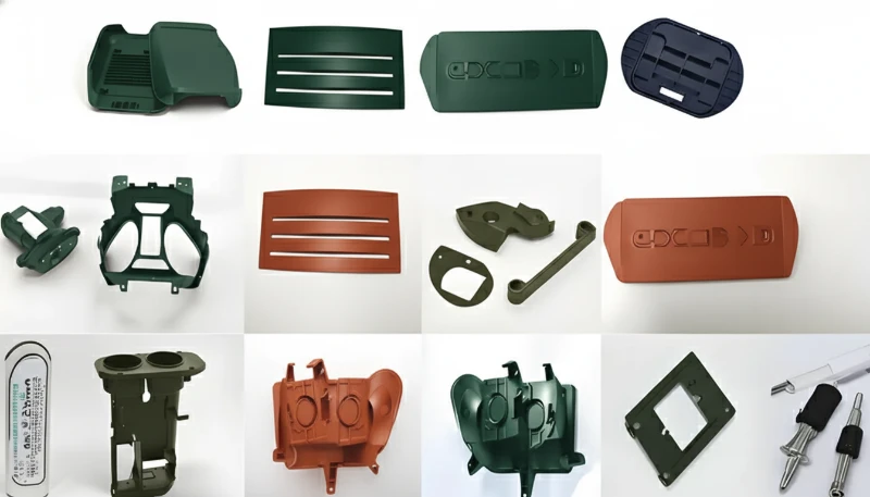
The manufacturing landscape is in a constant state of evolution, driven by the demand for faster innovation, greater customization, and more efficient production. For decades, injection molding has been the undisputed king of mass production, delivering millions of identical, high-quality plastic parts at an unbeatable per-unit cost. On the other end of the spectrum, 3D printing (or additive manufacturing) has emerged as the champion of rapid prototyping and complex, one-off creations.
For years, these two technologies were viewed as separate, almost opposing, forces. One was for scale, the other for speed and intricacy. But the future of manufacturing isn’t about choosing one over the other; it’s about intelligently integrating them. At ZetarMold, we stand at the forefront of this convergence, harnessing the power of both to offer our clients unprecedented flexibility, speed, and quality. This article explores the symbiotic relationship between 3D printing and injection molding and how their integration is building the factory of the future, today.
What are the fundamental differences between 3D Printing and Injection Molding?
To understand how these technologies integrate, it’s crucial to first appreciate their core principles and what makes them unique. They are fundamentally different approaches to creating a physical object.
3D Printing (Additive Manufacturing), as the name implies, builds objects additively. A digital 3D model (CAD file) is sliced into thousands of thin horizontal layers. A 3D printer then deposits, fuses, or cures material layer by layer until the final object is formed.
- Process: Layer-by-layer material addition.
- Strengths: Incredible geometric freedom (complex internal structures, organic shapes), no tooling required, fast for single parts or small batches, easy to iterate on designs.
- Weaknesses: Slower per-part speed in mass production, sometimes limited material properties compared to molded parts, can have visible layer lines requiring post-processing.
- Best for: Prototypes, custom jigs and fixtures, highly complex low-volume parts, and, as we’ll see, mold tooling itself.
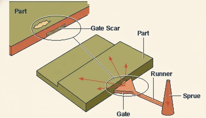
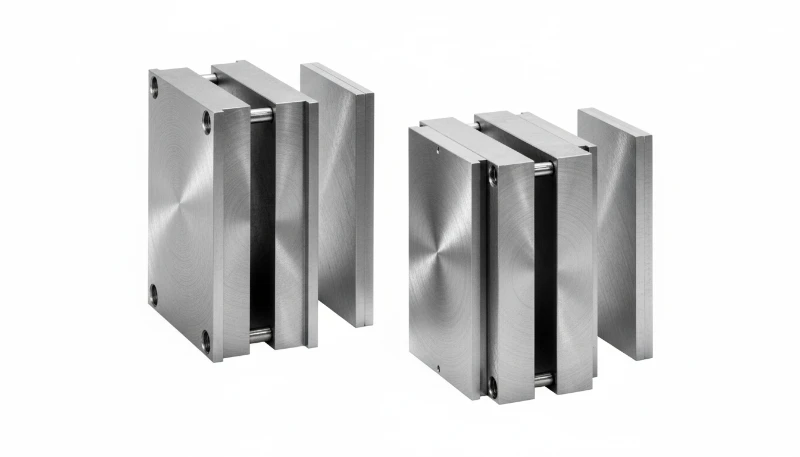
Injection Molding is a process rooted in mass production. It starts with the creation of a highly precise, robust mold (or “tool”), typically machined from steel or aluminum. This mold is the negative of the desired part. Molten thermoplastic material is then injected into the mold cavity under immense pressure. It cools, solidifies, and the finished part is ejected. This cycle repeats every few seconds.
- Process: Injecting molten material into a pre-made mold.
- Strengths: Extremely fast cycle times (seconds per part), very low per-part cost at high volumes, excellent surface finish, wide range of engineering-grade materials, high repeatability.
- Weaknesses: Extremely high upfront cost and long lead time for mold manufacturing (weeks to months), design changes are very expensive and difficult once the mold is made.
- Best for: Mass production of consumer products, automotive components, medical devices—anything requiring thousands to millions of identical parts.
The key takeaway is that their weaknesses are each other’s strengths. 3D printing1‘s high per-part cost and slowness at scale are non-issues for injection molding. Conversely, injection molding’s cripplingly high initial tooling cost and inflexibility are where 3D printing shines. This complementary nature is the foundation of their powerful integration, a service we specialize in at ZetarMold to deliver optimal manufacturing solutions.
How is 3D Printing Used for Rapid Prototyping in the Injection Molding Workflow?
“Using 3D printing for prototyping before creating an injection mold can significantly reduce the risk of costly tooling errors.”True
This is one of the most common and valuable applications of the technology. Creating a physical prototype allows for design validation, fit checks, and functional testing before committing tens of thousands of dollars and weeks of time to hard tooling. It’s a fundamental risk-mitigation strategy in modern product development.
“3D printed prototypes have the exact same mechanical properties as the final injection molded part.”False
While 3D printing materials have advanced significantly, the layer-by-layer additive process results in anisotropic properties (different strengths in different directions). An injection molded part is formed from a homogenous melt, giving it isotropic and generally superior mechanical properties like tensile strength and impact resistance. Prototypes are excellent for form and fit, but their functional performance is only an approximation of the final part.
This integration of additive manufacturing with traditional injection molding processes reflects a fundamental shift in how manufacturers approach product development. By leveraging the strengths of both technologies, companies can achieve faster time-to-market while maintaining the quality and consistency required for high-volume production. The key is understanding when to apply each technology and how they can complement each other throughout the product lifecycle, from initial concept validation through full-scale manufacturing.
One of the most established and valuable integrations of 3D printing is in the prototyping phase of a new injection molding project. The single greatest risk in injection molding is investing tens of thousands of dollars and months of waiting into a steel mold, only to discover a critical design flaw in the first batch of parts. Fixing a steel mold is an expensive, time-consuming, and sometimes impossible task.
This is where rapid prototyping with 3D printing becomes indispensable. Before a single chip of steel is cut, we can take your CAD design and 3D print a high-fidelity prototype in a matter of hours or days. This physical model can be used for:
- Form and Fit Testing: Does the part fit correctly into its larger assembly? Are the ergonomics right? A 3D printed model provides tangible answers that a screen cannot.
- Functional Testing: With advanced engineering-grade 3D printing materials, prototypes can often be used for limited functional testing, simulating the stresses and strains the final part will endure.
- Stakeholder Communication: A physical prototype is an incredibly powerful tool for communicating a design to marketing teams, investors, and clients. It makes the product real and allows for immediate, actionable feedback.
By using our rapid prototyping services, our clients can go through multiple design iterations in a single week. A flaw that might have cost $10,000 to fix in a steel mold can be corrected with a simple CAD file adjustment and a new $100 print. This “fail fast, fail cheap” approach de-risks the entire product development cycle and ensures that when you’re ready to commit to mass production, the design is already perfected and validated.
Can You Directly 3D Print Molds for Injection Molding?
Yes, and this is where the integration moves beyond prototyping and into the production workflow itself. Instead of using 3D printing to make the part, we use it to make the tool—the mold. This is a revolutionary step that directly addresses the primary drawbacks of traditional injection molding: high tooling cost and long lead times.
At ZetarMold, we can 3D print mold inserts or even entire small molds using specialized materials. There are two primary approaches:
- Polymer Molds: Using industrial 3D printers (like PolyJet or SLA technology), we can print molds from high-temperature, durable photopolymer resins. These molds are not designed to last for millions of cycles like steel, but they are perfectly capable of producing dozens, hundreds, or even a few thousand parts in the actual production-intent thermoplastic. The mold can be printed and ready for the injection press in 1-3 days.
- Metal Molds: Using a process called Direct Metal Laser Sintering (DMLS), we can 3D print molds from tool steel or aluminum. A high-power laser fuses fine metal powder layer by layer, creating a fully dense metal mold. These molds have a much longer lifespan than polymer molds and can be used for tens of thousands of shots.
The implications are enormous. A project that requires only 500 units would traditionally be prohibitively expensive for injection molding due to the tool cost. But with a 3D printed polymer mold, you can get 500 production-quality parts quickly and cost-effectively. This opens the door for low-volume production runs, limited editions, and extensive market testing with real parts.

What is “Bridge Tooling” and How Does 3D Printing Enable It?
Bridge tooling, also known as bridge-to-production, is a direct application of 3D printed molds. It serves as an intermediate manufacturing step that “bridges” the gap between the final prototype and full-scale mass production with hard tooling.
Imagine this scenario: your product design is finalized, and you’ve ordered a traditional steel production mold. The lead time is 10 weeks. However, you have a trade show in 4 weeks where you need to showcase the final product, or a key client needs 1,000 units immediately to start their own production line. Waiting 10 weeks is not an option.
This is the perfect use case for bridge tooling. By leveraging our bridge tooling solutions, we can 3D print a mold and inject those first 1,000 units for you in under two weeks. These are not prototypes; they are real injection-molded parts made from the final production material (e.g., ABS, Polypropylene, Nylon). This allows you to:
- Accelerate Time-to-Market: Launch your product and start generating revenue while the high-volume steel mold is still being manufactured.
- Satisfy Early Demand: Fulfill initial customer orders or provide pilot-run parts to key partners without delay.
- Conduct Real-World Testing: Use the first batch of parts for extensive market testing or to secure final regulatory approvals.
- Generate Early Cash Flow: Selling the parts produced via bridge tooling can help finance the cost of the final production tool.
Bridge tooling eliminates the painful waiting period typically associated with injection molding, transforming the production timeline from a sequential process to a parallel one. It’s a strategic tool that provides a powerful competitive advantage.
What are Conformal Cooling Channels and Why are They a Game-Changer?
“3D printed molds are ideal for producing a few hundred to a few thousand parts with the final production-intent material.”True
This is the core value proposition of bridge tooling. While they lack the extreme longevity of steel molds, 3D printed molds made from robust polymers or metal are more than capable of handling the temperatures and pressures of injection molding for low-to-mid volume runs. This allows companies to get real, sellable parts to market faster.
“A 3D printed mold can be used to produce millions of parts, just like a hardened steel mold.”False
This is incorrect. The materials and layer-based construction of 3D printed molds cannot withstand the thermal and mechanical stresses of millions of injection cycles. Polymer molds typically last for hundreds to low thousands of shots, while DMLS metal molds might reach tens of thousands. Hardened P20 or H13 steel molds are required for true mass production in the hundreds of thousands to millions of cycles.
This integration of additive manufacturing with traditional injection molding processes reflects a fundamental shift in how manufacturers approach product development. By leveraging the strengths of both technologies, companies can achieve faster time-to-market while maintaining the quality and consistency required for high-volume production. The key is understanding when to apply each technology and how they can complement each other throughout the product lifecycle, from initial concept validation through full-scale manufacturing.
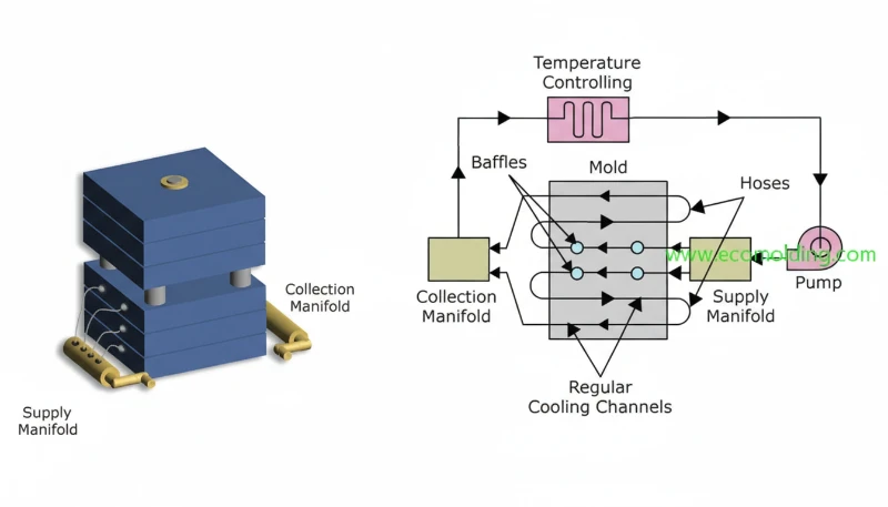
Perhaps the most sophisticated and impactful integration of 3D printing and injection molding lies within the mold itself, specifically in the cooling channels. In injection molding, cooling is everything. It often accounts for over 70% of the total cycle time and has the biggest impact on part quality and dimensional stability.
Traditionally, cooling channels are created by drilling straight lines through the steel mold block. This is effective, but highly inefficient. The straight channels cannot cool all areas of the part evenly, especially complex curves or deep features. This leads to longer cooling times, hot spots that cause warping, and sink marks on the final part.
Enter conformal cooling. Using metal 3D printing (DMLS), we can design and print cooling channels that precisely follow the 3D contours of the part, maintaining a uniform distance from the mold surface at every point. This is physically impossible to achieve with traditional drilling.
The results are transformative:
- Drastically Reduced Cycle Times: By cooling the part more quickly and evenly, conformal cooling can reduce cycle times by 30-70%. In a high-volume run, this translates to massive increases in productivity and lower per-part costs.
- Superior Part Quality: Uniform cooling minimizes the internal stresses that cause part warpage. It also eliminates hot spots, resulting in better surface finish and dimensional accuracy.
- Complex Designs Made Possible: For some highly complex part geometries, traditional cooling is simply not viable. Conformal cooling enables the successful molding of parts that were previously impossible to produce with high quality.
While a mold with conformal cooling2 is more expensive to produce upfront due to the metal 3D printing process, the ROI for high-volume production is often staggering. The savings from reduced cycle time and lower scrap rates can pay back the initial investment many times over. This is a high-performance solution that ZetarMold offers to clients looking to optimize their production to the highest degree.
How Does Hybrid Manufacturing Combine the Best of Both Worlds?
Hybrid manufacturing takes the integration of additive and subtractive processes to the next level. Instead of using two separate machines, a hybrid approach combines both capabilities into a single, seamless workflow. This allows for the creation of parts and tools that would be impossible or wildly impractical with either method alone.
In the context of mold making, a hybrid process might look like this:
- Additive Step: A metal 3D printing process (DMLS) is used to build the rough shape of a mold insert, including highly complex internal features like conformal cooling channels. This is called the near-net shape3.
- Subtractive Step: Without removing the part from the machine, a CNC milling head is brought in. It then machines the critical surfaces of the mold—the parting lines, the cavity surface, and injector pin holes—to an extremely high tolerance and a mirror-smooth finish.
This hybrid approach allows us to leverage 3D printing for what it does best (geometric complexity) and CNC machining for what it does best (precision and surface finish). There are no re-fixturing errors from moving the part between machines, and the entire process is streamlined. The result is a production mold with optimized performance (thanks to conformal cooling) and perfect precision, created more efficiently than a purely sequential process.
At ZetarMold, our integrated facility mirrors this hybrid philosophy. Our deep expertise in both additive manufacturing and high-precision CNC machining allows us to choose the most effective combination of processes to build the best possible tool for your specific application.
What are the Cost and Time Implications of Integrating 3D Printing?
The decision to integrate 3D printing into an injection molding project is a strategic one, based on volume, complexity, and time-to-market requirements. There isn’t a one-size-fits-all answer, but we can break down the cost-benefit analysis by application.
- For Prototyping: The benefits are unambiguous. 3D printing is orders of magnitude cheaper and faster than creating a prototype mold. It saves thousands of dollars and weeks of time, with the primary cost being the filament or resin and a few hours of print time.
- For Bridge Tooling (Low-Volume Production): Here, 3D printed molds shine. A printed polymer mold might cost $500 – $3,000 and take 2-5 days to produce. A comparable aluminum mold might cost $5,000 – $15,000 and take 2-4 weeks, while a steel mold would be even more. For runs under a few thousand parts, a 3D printed mold is almost always the most economical choice.
- For Production Tooling (with Conformal Cooling): This is a long-term investment. A steel mold with 3D printed conformal cooling channels will be more expensive upfront (20-50% more) than a conventionally made mold. However, the savings come during production. If the conformal cooling reduces the cycle time from 30 seconds to 20 seconds, you are producing 50% more parts in the same amount of time. Over a run of 500,000 parts, this time saving translates into massive cost reductions that far outweigh the initial tooling investment.
As your manufacturing partner, ZetarMold helps you navigate these decisions. We analyze your project goals—part volume, material requirements, and launch deadlines—to recommend the tooling strategy that delivers the best total value. You can contact us for a detailed quote to see how this applies to your project.
What Does the Future of Integrated Manufacturing Look Like?
The integration of 3D printing and injection molding is not a final destination; it’s an ongoing journey. We are just scratching the surface of what’s possible. As we look to the horizon, several key trends are set to further revolutionize the factory floor.
- Advanced Materials: New generations of printable polymers and metals will emerge, offering higher temperature resistance, greater durability, and novel properties, further closing the gap between printed molds and traditional tooling.
- AI and Generative Design: Artificial intelligence will play a larger role in optimizing tool design. Engineers will input constraints (e.g., cycle time, material, pressure), and AI algorithms will generatively design the most efficient mold, complete with incredibly complex, organic-looking conformal cooling networks that a human could never conceive.
- The Rise of the Digital Twin: Before any material is used, manufacturers will create a “Digital Twin of the entire production process. This virtual simulation will model the mold, the plastic flow, the cooling, and the final part properties, allowing for complete optimization in the digital realm before committing to physical production.
- Fully Automated Hybrid Systems: The hybrid manufacturing cells of today will become more widespread and automated. A single system will be able to take a CAD file, 3D print the mold, machine it, install it in a press, and begin injecting parts with minimal human intervention.
- Distributed Manufacturing: This integration enables a more decentralized production model. Companies can quickly produce bridge tooling for low-volume runs at a local facility like ZetarMold, serving regional markets faster while a centralized factory handles global mass production.
At ZetarMold, we are not just watching this future unfold; we are actively building it. By investing in the latest technologies and cultivating deep expertise in both additive and traditional manufacturing, we are positioned to guide our clients through this exciting new era of production.
The fusion of 3D printing’s agility with injection molding’s efficiency is creating a new paradigm in manufacturing—one that is more responsive, adaptable, and powerful than ever before. It’s a combination that unlocks new possibilities for designers, engineers, and businesses. Whether you need to accelerate your time-to-market, produce a low-volume run with production-grade materials, or optimize a high-volume process for maximum efficiency, this integrated approach holds the key.
Ready to harness the power of this manufacturing revolution for your next project? Contact the experts at ZetarMold today to discuss how we can turn your ideas into reality, faster and smarter than ever.
Frequently Asked Questions (FAQ)
1. How long does a 3D printed mold last?
The lifespan depends entirely on the material used for the mold. A mold printed from a standard photopolymer resin may last for 10-100 shots. A high-temperature, durable resin mold can often produce 100-2,000+ parts. A metal 3D printed mold (DMLS) can last for tens of thousands of cycles, making it suitable for larger production runs.
2. What materials can be injected into a 3D printed mold?
A wide range of common thermoplastics can be used, but process parameters must be carefully controlled. Materials like Polypropylene (PP), Polyethylene (PE), TPE, and ABS are frequently used with printed polymer molds. For higher-temperature engineering plastics like Nylon (PA) or Polycarbonate (PC), a more durable polymer mold or a metal 3D printed mold is required.
3. Is 3D printing replacing injection molding?
No. They are complementary technologies. 3D printing is not competitive for mass production (100,000+ parts) where injection molding’s speed and low per-part cost are unbeatable. Instead, 3D printing is enhancing injection molding by providing rapid prototypes, low-cost bridge tooling, and performance-enhancing features like conformal cooling.
4. When should I choose a 3D printed mold over a traditional steel mold?
Choose a 3D printed mold when your production volume is low (typically under 5,000 parts), when your time-to-market is critical and you can’t wait for a steel mold, or when you need to validate a design with a few hundred real parts before committing to expensive hard tooling. For high-volume, long-term production, a traditional steel mold is still the standard.
5. How do I get started with an integrated manufacturing project at ZetarMold?
It’s simple. Visit our contact page and send us your project details, including your CAD files, estimated annual volume, material requirements, and project timeline. Our engineering team will review your needs and recommend the most effective and economical manufacturing strategy, whether it involves rapid prototyping, bridge tooling, or a high-performance production mold. See our Supplier Sourcing Guide for a comprehensive overview.
See our Injection Molding Complete Guide for a comprehensive overview.
-
Conformal Cooling: A method of creating cooling channels within an injection mold that follow the shape or “conform” to the part’s geometry, rather than being restricted to straight, drilled lines. ↩
-
Near-Net Shape: An object produced by a manufacturing process (like casting or 3D printing) that is very close to the final, or ‘net’, shape of the product, minimizing the amount of finishing work (like machining) required. ↩
-
Digital Twin: A virtual model of a physical object or system that serves as its real-time digital counterpart. It can be used for simulation, monitoring, and analysis to predict and optimize performance before and during production. ↩
Need a Quote for Your Injection Molding Project?
Get competitive pricing, DFM feedback, and production timeline from ZetarMold’s engineering team.


