 Skip to content

Maintain uniform wall thickness between 0.5-4mm to prevent defects like warping and sink marks
Apply draft angles of 0.5-2° minimum to ensure proper mold release and part ejection
Design ribs at 60% of wall thickness to provide structural support without molding issues
Position gates strategically to optimize flow patterns and minimize visible gate marks
Design side actions and undercuts with proper clearances to avoid tool complexity
After twenty years of designing injection molded parts, I’ve seen countless projects succeed or fail based on fundamental design decisions made early in development. The difference between a part that molds beautifully and one that gives you headaches isn’t luck—it’s understanding how plastic flows, cools, and shrinks inside a mold cavity.
Most engineers approach part design thinking about function first, which makes sense. But in injection molding, manufacturability needs to be considered from day one. I’ve watched brilliant mechanical designs turn into production nightmares because nobody thought about how the plastic would fill the mold or how the part would eject cleanly.
This guide covers the essential principles I use when reviewing part designs. These aren’t theoretical concepts—they’re practical rules that determine whether your parts come out of the mold looking perfect or covered in flow lines, sink marks, and dimensional variations that make your quality team nervous.
What Are the Fundamental Principles of Injection Molded Part Design?
The most critical principle in injection molding is designing for material flow. Molten plastic behaves like thick honey under pressure, flowing preferentially through thick sections and hesitating at thin areas. Understanding this flow behavior guides every design decision from wall thickness to gate placement.
Wall thickness drives almost everything else about your part’s moldability. I recommend keeping walls between 0.5mm and 4mm for most applications, with thinner walls for small electronic housings and thicker sections for structural components. The key is maintaining consistency—thickness variations create differential cooling rates that lead to warping and internal stress.
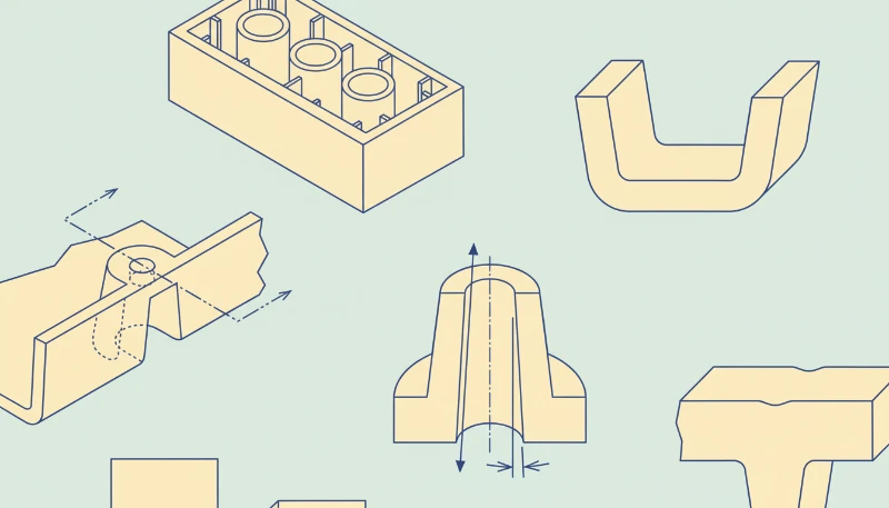
Design for ejection from the start. Every part needs to come out of the mold cleanly without damage or excessive ejection forces. This means incorporating draft angles, avoiding sharp corners that create stress concentrations, and planning ejector pin locations where they won’t compromise part appearance or function. Think about the molding process1 as you design—the mold needs to open, the part needs to fall out or be pushed out cleanly, and the cycle repeats thousands of times.
How Do Wall Thickness and Rib Design Affect Part Quality?
Wall thickness variations are the enemy of good injection molded parts. When I review designs, I look for thickness ratios first. Ideally, keep all walls within 25% of each other. If you need a thick boss or mounting feature, transition gradually using radii and tapers rather than sharp thickness changes that create sink marks on the opposite surface.
Sink marks occur when thick sections shrink more than surrounding thin areas during cooling. The classic example is a thick boss on the back of a thin housing wall—you’ll get a visible depression on the cosmetic surface every time. The solution is either redesigning to eliminate the thickness variation or adding ribs to the back of the boss to distribute the material more evenly.
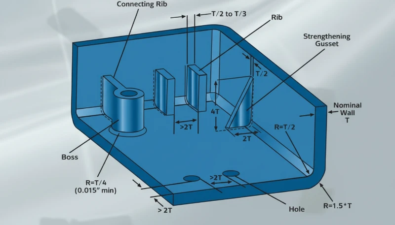
Ribs provide structural strength without adding bulk, but they need proper design ratios. I size ribs at 60% of the nominal wall thickness with draft angles on both sides. A 2mm wall gets 1.2mm thick ribs with 1° of draft minimum. Ribs that are too thick create their own sink marks, while ribs that are too thin don’t provide meaningful structural support and can be difficult to fill completely.
Why Are Draft Angles and Radii Critical for Mold Release?
Draft angles prevent parts from sticking in the mold and reduce ejection forces that can damage delicate features. I specify minimum 0.5° draft on all vertical surfaces, increasing to 1-2° for textured surfaces or deep cavities. The deeper the feature, the more draft you need—think of trying to remove a cake from a straight-sided pan versus one with angled sides.
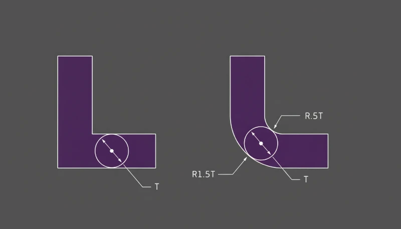
Sharp corners create stress concentrations and are impossible to machine properly. All internal corners should have radii equal to at least half the wall thickness. External corners can be smaller but should never be completely sharp. These radii also improve material flow around corners and reduce the risk of stress cracking in service.
Undercuts complicate mold design2 and increase tooling costs, but sometimes they’re unavoidable. When you must include undercuts, keep them shallow and accessible for side action mechanisms. Deep or complex undercuts require expensive tooling features and slow down cycle times as additional mold movements are required for each part.
What Are the Best Practices for Gate and Runner Design?
Gate location determines flow patterns, weld line placement, and surface finish quality. I prefer gating into the thickest section of the part where possible, allowing plastic to flow outward into thinner areas. This approach minimizes short shots and ensures complete filling of extremities.
Gate size affects injection pressure requirements and gate vestige appearance. Smaller gates require higher injection pressures but create smaller witness marks when trimmed. For cosmetic parts, position gates on non-visible surfaces or in areas where gate marks won’t affect function. Sometimes adding a small gate tab that can be cleanly trimmed is better than trying to hide a gate in a difficult location.
Runner systems should provide balanced flow to all cavities in multi-cavity molds. Unbalanced runners create parts with different filling characteristics, leading to dimensional variations between cavities. Cold runner systems are simpler and less expensive, while hot runner systems eliminate runner waste and can improve cycle times for high-volume production.
How Do You Design Undercuts and Side Actions?
Undercuts require side actions, slides, or lifters in the mold, adding complexity and cost. Before incorporating undercuts, explore alternatives like assembly methods, living hinges, or redesigning the feature entirely. Sometimes splitting a part into two components is more economical than creating complex tooling for undercuts.
When undercuts are necessary, keep them shallow and design adequate clearance for the side action mechanism. The mold builder needs space for the slide mechanism and sufficient steel for strength. Deep undercuts or those with complex geometries can require expensive tooling solutions that impact both initial tooling cost and maintenance requirements.
Side actions must sequence properly with the main mold opening. This typically means the side action retracts first, then the main mold opens, and finally the part ejects. Complex sequencing increases cycle time and requires more sophisticated mold controls. Design undercuts to allow the simplest possible side action mechanism—straight pulls are better than angled actions, and cam-actuated slides are more reliable than hydraulic systems.
What Tolerance Standards Apply to Injection Molded Parts?
Injection molding tolerances depend on part size, material properties, and mold construction quality. For general dimensions, I specify ±0.1mm for features under 25mm, increasing to ±0.2mm for larger dimensions. Tight tolerances are achievable but expensive—they require precision tooling, careful process control, and potentially secondary operations.
Shrinkage varies by material and part geometry. Crystalline materials like nylon and POM shrink more than amorphous materials like ABS and polycarbonate. Part geometry affects shrinkage patterns—thick sections shrink more than thin sections, and long dimensions across the grain direction typically shrink less than those parallel to flow.
Warpage is the most challenging tolerance issue in injection molding. Parts with asymmetric geometry, varying wall thickness, or long unsupported sections are prone to warpage. The best approach is designing symmetry into parts where possible and using ribs or other structural features to resist distortion. Post-molding fixtures can help with some warpage issues but add cost and complexity to production.
What Are the Most Frequently Asked Questions About Injection Molded Part Design?
What’s the minimum wall thickness for injection molded parts?
Minimum wall thickness depends on material properties and part size. For most engineering plastics, 0.5mm is the practical minimum for small parts, while larger parts typically require 0.8mm or thicker walls for adequate strength and fillability. Very thin walls are difficult to fill completely and may not provide sufficient mechanical properties. I recommend staying above 0.7mm unless you have specific requirements for thin walls and are prepared for potential molding challenges like incomplete filling or high injection pressures.
How do I prevent sink marks on thick sections?
Sink marks result from differential shrinkage between thick and thin sections. The best prevention is avoiding thickness variations altogether, but when thick sections are necessary, several strategies help. Core out thick sections where possible, transition gradually between different thicknesses using radii rather than sharp changes, and consider adding ribs to the back of thick features to distribute material more evenly. Sometimes redesigning the part to eliminate thick sections entirely is the most effective solution, even if it requires assembly of multiple components.
What draft angles should I use for different surface textures?
Smooth surfaces require minimum 0.5° draft, but textured surfaces need significantly more. Light textures like EDM finish require 1° per 0.025mm (0.001″) of texture depth. Heavy textures or complex surface patterns may need 3-5° of draft. The rule is that deeper textures require more draft because they create more surface area contact with the mold. If appearance requirements limit draft angles, consider using slides or other mold mechanisms to achieve proper release, though this increases tooling complexity and cost.
Can I design living hinges in injection molded parts?
Living hinges work well in specific materials, particularly polypropylene and some TPE compounds. The hinge area should be very thin (0.2-0.4mm) with the thin section perpendicular to the hinge axis. Gate placement is critical—flow should cross the hinge line to align polymer chains properly for flex life. Design generous radii on both sides of the hinge and avoid sharp transitions that create stress concentrations. Living hinges require careful process control and material selection, but they eliminate assembly operations and create reliable, long-lasting flex connections when designed properly.
How do I design snap-fit features for injection molded assemblies?
Snap-fit design requires understanding material properties, particularly flexural modulus and strain-to-break values. Keep stress levels below 50% of the material’s yield strength to prevent creep and stress cracking. Design adequate lead-in chamfers for easy assembly and include features that limit deflection to prevent over-stressing. Cantilever beams are the most common snap-fit geometry, but annular snaps and interlock features work well for specific applications. Always prototype snap-fits early in development to validate engagement force and retention strength under realistic conditions.
What’s the difference between family molds and dedicated cavity molds?
Family molds produce multiple different parts in one shot, while dedicated molds produce multiple identical parts. Family molds work best when parts have similar volumes and wall thicknesses, requiring balanced runner systems and compatible process parameters. They’re cost-effective for low-volume production of related parts but can be challenging if parts have different shrink rates or optimal process conditions. Dedicated multi-cavity molds are simpler to balance and optimize but require higher volumes to justify the increased cavity count. Consider your volume requirements and part compatibility when choosing between these approaches.
How do I specify parting line locations for best results?
Parting lines should be located on non-cosmetic surfaces where possible, following the part’s natural geometry rather than cutting across smooth surfaces. The parting line determines draft direction and affects ejection strategy, so consider both cosmetic and functional requirements. Complex parting lines increase tooling costs and may create difficult-to-machine geometries. Sometimes accepting a parting line in a visible area is better than creating expensive tooling features to hide it. Work with your mold designer early to establish parting line locations that balance cosmetic requirements with practical manufacturing3 considerations.
What materials work best for transparent injection molded parts?
Polycarbonate, acrylic, and styrene-based materials offer excellent transparency but each has specific design requirements. Gate placement is critical—use film gates or pin gates positioned to minimize flow lines across optical surfaces. Uniform wall thickness prevents optical distortion from stress patterns. Design generous radii to eliminate sharp corners that can cause stress whitening. Consider assembly methods that don’t require snap-fits or press-fits that could create stress cracking. Post-molding annealing can relieve internal stresses and improve optical clarity, but adds cost and processing time to production.
Why Choose ZetarMold for Your Injection Molded Part Design Project?
ZetarMold brings two decades of injection molding expertise to every design review and manufacturing project. Our team of 8 design engineers works directly with clients to optimize part designs for manufacturability, drawing on experience from thousands of successful projects across automotive, medical, consumer, and industrial applications. We catch potential issues early in the design phase, preventing costly revisions and production delays later.
Our 400+ available resins and comprehensive quality certifications ensure we can match your material requirements while maintaining consistent production quality. With over 30 English-speaking staff members, communication remains clear throughout your project, from initial design review through final production. Our 92% first-pass yield rate reflects our commitment to getting parts right the first time, reducing your development timelines and total project costs.
Need a Quote for Your Injection Molding Project?
Get competitive pricing, DFM feedback within 48 hours, and production timelines from ZetarMold’s engineering team.
-
Molding Process: The complete injection molding cycle including material preparation, injection, cooling, and ejection phases that determine final part quality and production efficiency ↩
-
Mold Design: The engineering discipline of creating tooling that shapes molten plastic into finished parts, including cavity design, cooling systems, and ejection mechanisms ↩
-
Manufacturing: The production phase where validated molds and optimized processes create finished parts at scale with consistent quality and dimensional accuracy ↩


