 Skip to content

Your production run is humming along. Then, on shot 60,000, a customer emails a photo of flash on your part — the kind that jams their assembly fixture at 2 a.m. You replay the last three months and realize: nobody looked inside that mold after shot 50,000.
Mold inspection is the systematic examination of an injection mold to detect wear, contamination, dimensional drift, and damage before they generate scrap or stop a production line. Done right, it is the single highest-ROI activity in tooling management. Done poorly — or skipped — it turns a $200 cleaning visit into a $20,000 emergency repair.
- Mold inspection catches wear and contamination before they cause scrap or unplanned downtime.
- A structured inspection schedule — triggered by shot count, not calendar — is more reliable than interval-based plans.
- The parting line, vents, and ejector pins are the three highest-wear zones in any production mold.
- Preventive inspection every 50,000 shots costs a fraction of one unplanned production shutdown.
- Combining visual checks, dimensional measurement, and functional tests gives the most complete picture of mold health.
What Is Mold Inspection?
Mold inspection is a structured evaluation of every functional zone of an injection mold — cavity surfaces, parting line1, vents, runners, ejector system, cooling channels, and clamping components — to measure wear, detect contamination, and confirm dimensional accuracy against original specifications.
It is not a casual visual pass. A proper inspection uses a defined checklist, calibrated measurement tools (dial indicators, air gauges, borescopes for cooling channels), and documented results that are compared against the baseline from when the mold was first qualified. The output is not a pass/fail stamp — it is a prioritized action list: clean now, monitor these, replace before next run.
The distinction between inspection and maintenance matters. Inspection is diagnostic: you find out what the mold’s current condition is. Maintenance is corrective: you act on what inspection revealed. Skipping inspection and going straight to a scheduled cleaning is like changing your car’s oil on a fixed date without checking the engine warning light — you might be cleaning a fine mold and ignoring a cracked ejector pin at the same time.
Why Mold Inspection Matters More Than Most Teams Think
Flash develops in less than 3,000 shots once a parting line begins to wear beyond 0.05mm — and it accelerates from there. By the time a quality inspector catches the flash at final inspection, the mold has typically run 5,000–10,000 bad shots. That’s not a defect problem; it’s an inspection-gap problem.

The real cost argument for inspection comes down to three categories. First, scrap and rework: a mold producing 2% flash on a 16-cavity tool at 1,000 shots/hour wastes 320 parts per hour. At $0.50/part, that’s $160/hour in scrap — $3,840 in a 24-hour shift. Second, emergency repair: unplanned mold pulls require expedited machining, often at 2–3× standard shop rates, plus line shutdown costs. Third, tooling life reduction: contamination left inside cooling channels raises mold temperature, accelerates steel fatigue, and can cut mold life by 30–40%.
Inspection, by contrast, costs time and a technician. For a mid-size production mold, a thorough inspection at 50,000 shots takes 4–8 hours plus parts cost. The math is straightforward: even one prevented shutdown justifies a full year of scheduled inspections.
At ZetarMold, we run mandatory mold inspection every 50,000 shots for production tools. Tools that skip scheduled inspection develop flash 3× faster — a preventive clean at 50k shots costs less than 1% of an unplanned production shutdown that halts a customer’s assembly line.
The Six Zones Every Mold Inspection Must Cover
Six zones account for 90%+ of all mold failures; a thorough inspection covers all of them systematically.
Zone 1 — Parting Line and Mold Face: The parting line is the primary wear point in any mold. Check for surface damage, metal deformation, and gaps that would allow flash. Use a feeler gauge across the full perimeter; any reading above 0.03mm in a precision mold is a flag. Inspect the mold face for pitting, rust, or deposits from plastic degradation.
Zone 2 — Cavity and Core Surfaces: Examine cavity surfaces with a bright light and magnifier. Look for scratches, erosion near gates, buildup of degraded material, and any surface finish changes that would telegraph to the part. Compare surface roughness to the original finish record if one exists. For optical or Class-A parts, any visible mark on the cavity is a reject-generating defect.
Zone 3 — Venting: Vents clog with every shot cycle as volatiles from the plastic deposit on the vent land. A blocked vent raises cavity pressure, burns the plastic at the last-fill point, and can crack the steel over time. Vent depth and land width should be measured against specification — typical vent depths are 0.015–0.025mm for amorphous resins, 0.025–0.038mm for semi-crystalline.
| Zone | Key Check | Tool | Action Threshold |
|---|---|---|---|
| Parting Line | Gap / flatness | Feeler gauge | > 0.03mm → flag |
| Cavity / Core | Surface condition | 10× loupe, LED light | Any pitting or scratch → document |
| Venting | Vent depth & cleanliness | Depth micrometer | Blocked or out-of-spec → clean |
| Ejector System | Pin diameter, binding | Pin gauge, manual stroke | Binding or undersize → replace |
| Cooling Channels | Scale, flow rate | Borescope, flow meter | 15% flow drop → descale |
| Runner / Gate | Erosion measurement | Depth micrometer | > 0.1mm erosion → replace insert |
Zone 4 — Ejector System: Check every ejector pin for burrs, bends, and binding. A single stuck pin can crack the part, mar the surface, or cause the mold to hang open under clamp pressure. Check return springs for fatigue and make sure the ejector plate travels freely through its full stroke. Ejector pin holes should be measured for roundness if the tool has run more than 500,000 shots.
Zone 5 — Cooling System: Cooling channel inspection is the most overlooked and most impactful zone. Scale buildup of just 0.25mm reduces heat transfer efficiency by 40%. Use a borescope to check channel walls; measure inlet and outlet water temperature differential (target: within 3°C across the mold). Flow rate should be checked against baseline — a 15% drop indicates partial blockage.
Zone 6 — Runner and Gate: Inspect runner and gate geometry for erosion, especially on gates running glass-filled or abrasive resins. Gate erosion widens effective gate size, increases material shear, and can introduce weld line2 defects as flow dynamics change. Measure gate width and depth against print; replace inserts when erosion exceeds 0.1mm.
After completing all six zones, the inspection record should document: zone condition (good/monitor/action required), measurement values versus baseline, photos of any anomalies, and the recommended action with urgency (before next run / within 10,000 shots / at next scheduled PM).
One practical note: if your mold doesn’t have a baseline record — measurements taken at T1 qualification — the first inspection becomes the baseline. It’s better to start now than wait for a pristine starting point that may never come.
How to Build an Inspection Schedule That Actually Works
An effective inspection schedule is triggered by shot count, not calendar time — because a mold running 24/7 needs inspection far sooner than one running two shifts per week.
“Shot count is a more reliable inspection trigger than elapsed calendar time.”True
Mold wear is directly proportional to cycles run, not days elapsed. A mold running three shifts per day accumulates 50,000 shots in roughly three weeks; the same mold running one shift per day takes nine weeks. Calendar-based schedules either under-inspect high-output tools or waste time on idle ones.
“All molds should follow the same inspection interval regardless of material or cavity count.”False
Glass-filled nylon running in a 32-cavity tool generates far more abrasive wear per unit time than unfilled ABS in a 4-cavity tool. Inspection frequency must scale with material abrasiveness, cavity count, and criticality of the part. A one-size schedule will either under-protect high-wear tools or waste resources on low-risk ones.
A practical tiered schedule for injection molds looks like this. At 10,000 shots: quick visual check — parting line flash, part appearance, any unusual sounds or cycle variation. At 50,000 shots: full inspection covering all six zones, vent cleaning, ejector pin lubrication, cooling channel flow test. At 200,000 shots: dimensional audit of cavity and core, gate wear measurement, ejector pin diameter check, steel hardness spot-check at high-wear zones. At 500,000+ shots: complete dimensional survey, cooling channel descaling, guided wave ultrasonic inspection of steel for subsurface cracks.
These intervals compress or expand based on material. Running 30% glass-filled nylon: halve the intervals. Running standard unfilled PP: extend by 30–50%. Running corrosive materials (PVC, flame-retardant grades with halogen content): add a monthly pH test of the cooling water and an annual corrosion inhibitor flush.
| Material | Abrasiveness | Recommended Inspection Interval | Priority Zone |
|---|---|---|---|
| Unfilled PP / PE | Low | Every 75,000 shots | Vents, cooling |
| ABS / HIPS | Low-Medium | Every 50,000 shots | Parting line, vents |
| PA6 / PA66 unfilled | Medium | Every 50,000 shots | Gate, cooling |
| PA66-GF30 | High | Every 25,000 shots | Gate, cavity, ejectors |
| POM (Acetal) | Medium | Every 40,000 shots | Vents, cavity surface |
| PVC / Halogenated FR | Corrosive | Every 30,000 shots + pH test | Cooling, parting line |
Document every inspection in a mold log — either a physical binder stored with the mold or a digital record in your ERP/MES. The log should include: mold ID, shot count at inspection, inspector name, condition by zone, photos of wear areas, actions taken, and next inspection trigger. A mold without a complete log is a liability: when something fails, you have no data to determine whether it was a maintenance failure or a design limitation.
Common Mold Defects Caught by Inspection — and Their Root Causes
Inspection catches five defect categories responsible for over 80% of mold-related production failures.
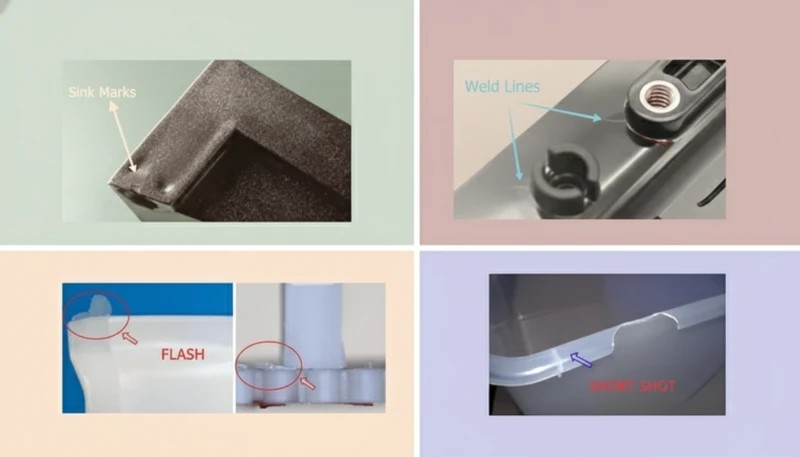
Flash is the most common and most visible mold defect. It appears as thin fins of plastic along the parting line, at vent locations, or around ejector pins. Root cause: worn or damaged parting line surfaces, insufficient clamp force for the material’s viscosity, or vents that have been cleaned to the wrong depth and now allow material to enter. Inspection catch point: parting line flatness check and feeler gauge test.
Short shots — parts that are incompletely filled — often trace back to blocked vents, not just process parameters. When gas cannot escape the cavity fast enough, it creates a back-pressure zone that stops the flow front. Inspection catch point: vent depth and condition measurement.
Sink marks and weld line defects can develop progressively as cooling channels scale up. A 0.5mm scale layer can raise cavity surface temperature by 8–12°C, changing material viscosity at the flow front and worsening weld line strength. Inspection catch point: cooling channel borescope inspection and inlet/outlet temperature differential.
Ejector and Surface Defects
Ejector pin marks and part distortion indicate worn or misaligned ejector components. When pins begin to bind, they exert uneven force on the part during ejection, causing distortion, surface marks, or outright cracking of the part. Inspection catch point: ejector pin diameter check and binding test (manual actuation of the ejector plate).
Surface finish degradation — visible on optical or Class-A parts as haze, drag marks, or texture loss — can result from cavity corrosion, gate erosion depositing material on the cavity wall, or microscopic surface cracking in the steel. Inspection catch point: cavity surface examination and comparison to the original surface finish standard.
“Blocked vents are a leading hidden cause of short shots, separate from injection parameters.”True
When vents clog with plastic volatiles and debris, gas trapped in the cavity resists the flow front. The injection machine sees rising pressure and the operator increases fill speed — making the gas compression problem worse. The root cause is a maintenance issue, not a process issue. Inspection and vent cleaning resolve it; increasing injection pressure does not.
“draft angle3 wear is visible to the naked eye during a quick visual check.”False
Draft angle erosion of 0.1–0.3° — enough to cause consistent ejection drag or part surface damage — is invisible without dimensional measurement. A visual inspection will show the part surface marks after the fact, but by then, hundreds or thousands of parts have already been affected. Proactive measurement of draft angle surfaces with a profilometer or contour gauge is the only reliable detection method.
One rule of thumb from the shop floor: if you can see a defect in the finished part and it showed up gradually over thousands of shots, it almost certainly had a mold inspection window where it could have been caught and corrected cheaply. The gradual onset of flash, short shots, and sink marks is the signature of progressive wear — exactly the type of deterioration inspection is designed to intercept.
Tools and Techniques for Better Mold Inspection
A well-equipped mold inspection station uses six categories of tools, each serving a different diagnostic purpose.
Visual inspection tools: bright LED work lights (minimum 5,000 lux), 10× and 30× magnifying glasses or loupe, fiber-optic light guides for deep cavity access. These are the entry-level tools every toolroom must have. They catch surface damage, contamination, rust, and obvious wear.
Dimensional measurement: dial indicators (0.001mm resolution) for parting line flatness, pin gauges for ejector pin holes and gate dimensions, depth micrometers for vent depth, optical comparators or CMM for full cavity surveys. Dimensional measurement turns a qualitative observation into a trackable number.
Cooling system diagnostics: industrial borescopes (5–8mm diameter, 1m length) for channel wall inspection, clamp-on flow meters for water flow rate, digital thermometers for inlet/outlet temperature differential. Cooling system health is the hardest zone to inspect visually from the outside — borescopes are the only way to see channel walls without disassembly.
Advanced Inspection Methods
Non-destructive testing (NDT): dye penetrant testing (PT) for surface crack detection in steel, ultrasonic testing (UT) for subsurface crack detection in high-cycle molds, eddy current testing for hardness verification at wear zones. NDT is typically reserved for molds past 500,000 shots or any mold that has experienced a crash, overload, or unexplained failure.
Documentation tools: camera with macro capability for photographing wear areas, digital calipers with data output for logging measurements directly to a spreadsheet, a standardized inspection form (either paper or tablet-based) that ensures every zone is checked every time.

The most important tool upgrade most shops can make is not a better borescope or a CMM — it’s a consistent inspection form. Without a structured checklist, inspection quality depends entirely on who’s doing it and how much time they have. A form forces completeness. It also creates the historical record that makes trend analysis possible: when did the parting line first show measurable wear? How fast is it progressing? Those answers determine whether the mold can run another 50,000 shots or needs to come out now.
For molds supporting injection mold design with tight tolerances, adding a mold flow simulation re-run after major repairs helps confirm that corrected geometry still fills properly before committing to production.
How to Improve Your Mold Inspection Program
Improving mold inspection is not about buying better equipment — it’s about building a system that catches deterioration at the earliest possible stage and documents findings well enough to enable data-driven decisions.
Steps 1–3: Build the Foundation
Step 1: Audit your current mold log completeness. Go through every production mold and check whether it has a mold log with shot count records, last inspection date, and condition history. For most shops, this audit reveals that 30–50% of tools have incomplete or no records. That’s the starting gap — filling it is the highest-priority improvement.
Step 2: Convert to shot-count-based triggers. If you’re currently scheduling inspection by calendar month, transition to shot-count triggers. This requires integrating shot counter data from the injection machines into your scheduling system. Most modern injection molding machines provide shot count data via Euromap or OPC-UA interface; older machines may need a simple mechanical counter retrofit costing under $200.
Step 3: Standardize your inspection checklist. Create a single-page form covering all six zones. Every inspector uses the same form, records measurements (not just pass/fail), and signs off. Review the forms monthly to identify trends across the tool fleet.
Steps 4–6: Drive Continuous Improvement
Step 4: Implement early-warning metrics from production data. Shot-to-shot cycle time variation of more than ±0.5 seconds is often the earliest signal of a mold problem — before any defect is visible on the part. Cavity pressure sensor data (if fitted) can show filling imbalance developing over thousands of shots. These leading indicators allow you to pull the mold for inspection before defects start.
Step 5: Train operators to report anomalies in real time. The person running the press is the first line of mold monitoring. Unusual sounds, visible flash on part 1 of a shift, or sticking at ejection are all inspection triggers — but only if the operator knows to escalate immediately rather than continuing to run and hoping it resolves. A simple ‘stop and call’ protocol for specific abnormalities pays for itself the first time someone catches an ejector pin starting to bind.
Step 6: Close the loop between inspection findings and design. When the same zone fails repeatedly — for example, the gate area eroding every 30,000 shots despite scheduled maintenance — that’s a design signal, not just a maintenance problem. The fix may be a harder gate insert material, a geometry change, or a mold flow analysis to understand why shear stress is concentrating there. Inspection data that feeds back into design improvement is the highest-level use of the information.
These six steps are not a one-time project — they are an ongoing operating discipline. The shops that execute them consistently report fewer emergency mold pulls, longer average tool life, and lower scrap rates. In our experience running 47 injection molding machines across three shifts, the gap between a well-run inspection program and a reactive maintenance approach typically represents 15–20% of total tooling cost per year in avoidable expenses.
One final practical note: start with the tools you have. A feeler gauge, a bright flashlight, and a notebook are enough to begin capturing baseline data on your highest-priority molds. Perfect equipment comes later — after you’ve proven the discipline. The discipline of looking — consistently, with documentation — is what matters most in the early stages of any inspection program. You cannot improve what you do not measure, and you cannot measure what you do not inspect on a consistent, documented schedule.
Where to Start
For teams moving toward low-volume injection molding or prototype tooling, inspection intervals can be lighter, but the same six-zone framework still applies. The goal is always the same: know the mold’s current condition before the next run, not after the next problem surfaces in production.
The most common question we hear from customers upgrading their inspection program is: ‘Where do we start?’ The answer is always the same — start with your highest-volume, highest-risk tool. Find its mold log (or create one from scratch using today as day zero). Pull the mold from the press, inspect it across all six zones using the checklist in this article, and record every measurement you take, not just the zones that look bad. Schedule the next inspection by shot count based on the material and cavity count. Everything else — better tools, data integration, operator training — follows naturally from that first properly documented inspection cycle.
Frequently Asked Questions About Mold Inspection
How often should an injection mold be inspected?
For standard production molds, inspect every 50,000 shots at minimum. High-wear applications — glass-filled resins at 30% or higher, high-cavity-count tools, or corrosive materials like PVC — require inspection every 25,000 shots. Low-volume prototype molds with unfilled materials can extend to 100,000 shots between full inspections. Always trigger inspection by shot count, not calendar time. A mold running one shift per week accumulates cycles far more slowly than a 24/7 production tool, so calendar-based scheduling will either over-inspect or under-inspect depending on production volume.
What are the most common defects found during mold inspection?
Flash along the parting line accounts for 35–40% of defects found during routine mold inspection, followed by blocked vents (25%), ejector pin wear or binding (15%), cavity surface contamination or damage (12%), and cooling channel scaling (8%). Each defect type maps directly to a specific inspection zone and measurement method. Flash indicates parting line wear; short shots indicate vent blockage; surface marks indicate ejector issues; sink marks or dimensional drift often trace back to cooling system scaling that raises cavity temperature and changes fill dynamics.
Can mold inspection be done without removing the mold from the press?
Partial inspection can be done in-press between shots: visual check of the parting line for flash, part surface examination for drag marks or surface finish changes, and flash detection at vent locations. However, a full inspection — covering vents, cooling channels, ejector system, and cavity dimensions — requires the mold to be pulled from the press and placed on an inspection bench with proper lighting and measurement tools. In-press checks serve as early-warning monitoring between full scheduled inspections, but they do not replace thorough off-press evaluation.
What is the cost of a typical mold inspection?
A full inspection for a mid-complexity two-plate mold runs 4–8 technician hours, costing $200–$600 in labor plus consumables used in cleaning and lubrication. Add dimensional measurement time — typically 2–4 additional hours — if a full cavity survey is included. This total of $400–$1,000 compares directly to the cost of a single unplanned production shutdown, which typically runs $5,000–$50,000 in lost production, expedited repair charges, and customer penalties. Scheduled inspection at 50,000 shots pays for itself the first time it prevents an emergency mold pull.
What tools are required for a professional mold inspection?
Essential tools include a bright LED work light (minimum 5,000 lux), 10× magnifying glass or loupe, feeler gauges for parting line gap measurement, dial indicator for flatness checks, pin gauge set for ejector holes and gate dimensions, depth micrometer for vent depth measurement, and a digital camera for documentation. Advanced inspection adds an industrial borescope (5–8mm diameter) for cooling channel inspection, portable CMM or optical comparator for cavity dimensional audit, and a dye penetrant kit for surface crack detection. Most shops begin with the essential set and add advanced tools as mold complexity and production volumes increase.
How does mold inspection relate to mold maintenance?
Inspection is diagnostic; maintenance is corrective. Inspection identifies what needs to be done — clean the vents, replace a worn ejector pin, descale a cooling channel. Maintenance carries out those actions. Running maintenance on a fixed schedule without prior inspection means you may be spending time cleaning a mold that is in perfectly good condition while ignoring a cracked component in an adjacent tool. The correct sequence is always inspection first, followed by targeted maintenance actions based on findings. This approach prevents both under-maintenance and wasted maintenance labor.
What records should be kept for each mold inspection?
Record the shot count at the time of inspection, the date, and the inspector’s name. Document the condition rating for each of the six zones — cavity surface, parting line, vents, ejector system, cooling channels, and runner/gate — with actual measurement values compared against baseline, not just a pass/fail rating. Photograph any wear areas or anomalies. Document actions taken during this inspection and set the next inspection trigger by shot count. A complete mold log enables trend analysis across multiple inspection cycles, which is the most valuable intelligence any inspection program can generate.

Quick rule: inspect at 50,000 shots for standard tools, 25,000 for abrasive materials. Log every finding with measurements, not impressions. If the same zone fails twice in a row, treat it as a design signal — not just a maintenance problem. And if your molds don’t have shot count records, start keeping them today; that data is the foundation everything else is built on.
-
parting line: A parting line is the seam on a molded part where the two halves of the mold meet and separate during ejection; it is often the first indicator of mold wear or flash development, and its flatness is measured in every structured mold inspection. ↩
-
weld line: A weld line refers to the visible seam formed when two plastic flow fronts meet inside the mold cavity and fuse incompletely, typically indicating a cooling or pressure imbalance that inspection can reveal. ↩
-
draft angle: Draft angle is measured in degrees and refers to the taper applied to vertical mold surfaces so the part releases cleanly during ejection; insufficient draft is a common root cause of ejection damage detected in routine inspection. ↩


