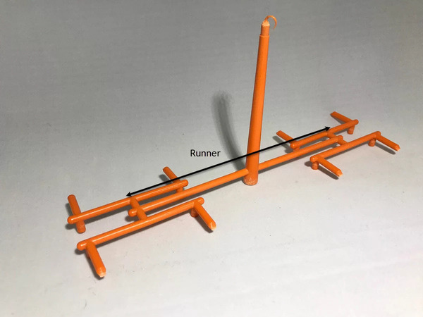
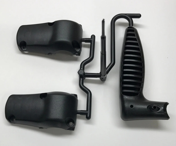
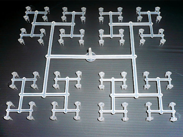
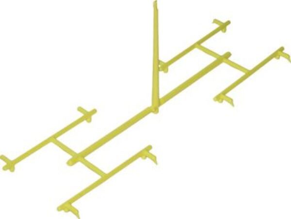
In injection molding, sprues and runners are essential components that direct molten plastic into the mold cavities, playing a vital role in the efficiency of the manufacturing process.
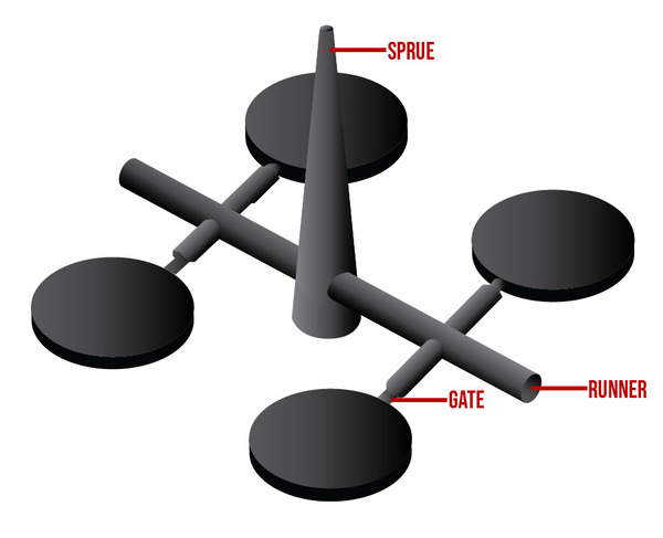
Sprues are vertical channels that transport molten plastic from the injection unit to the runner system, while runners are horizontal pathways that distribute the plastic to multiple cavities within the mold. Proper design of both sprue and runner can significantly reduce waste and improve cycle times.
This overview distinguishes between sprues and runners, but it’s crucial to understand their design implications to enhance production efficiency. Dive deeper to learn how optimizing these elements can lead to better quality parts and cost savings.
Sprues are responsible for transporting plastic to the runners.True
Sprues act as the primary channel that feeds molten plastic into the runner system, which then directs it to individual mold cavities.
Runners and sprues are interchangeable terms in injection molding.False
Although both are used to guide molten plastic, sprues specifically refer to the entry point from the injection unit, while runners are the channels that distribute the plastic to the cavities.
What are the Basic Concepts of Gates and Runners?
Gates control the entry of plastic into the mold, while runners serve as channels that guide the plastic to different cavities. Proper design of gates and runners enhances efficiency, reduces material waste, and improves the overall consistency of molded parts. Common types of gates include edge, pin, and tunnel gates, each suited for specific applications in industries such as automotive, consumer goods, and medical devices.
Sprue
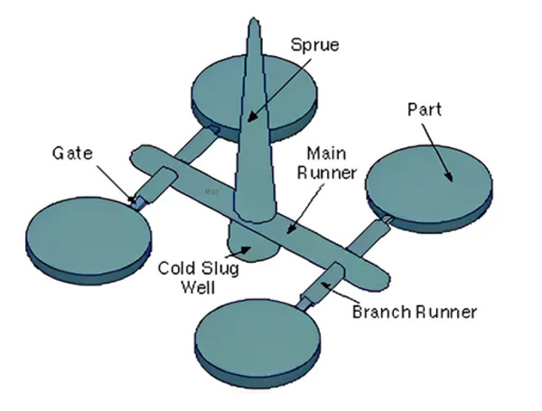
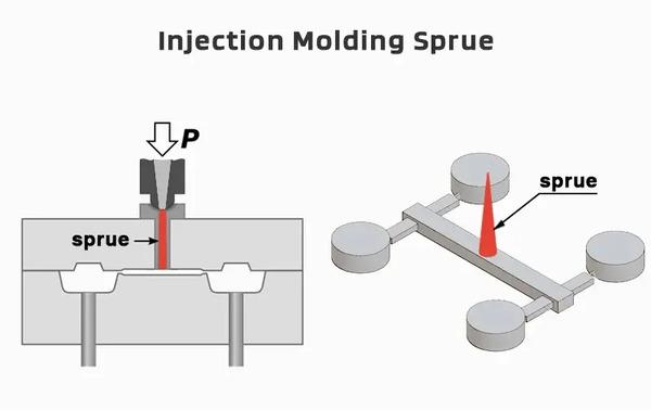
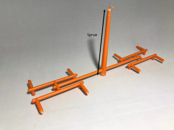
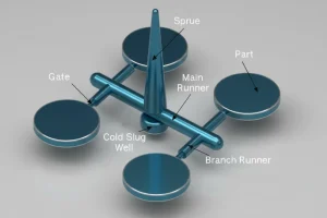
A sprue (runner inside the sprue bushing) is the channel in an injection mold that links the injection molding machine\’s nozzle to the runner system inside the mold. This channel serves as the initial entry point for molten plastic enters the mold\’s cavity and typically has a cone shape, which helps promote an unobstructed flow while also making it easier to remove the material after it solidifies. Not only does the design of a sprue have direct implications for how well plastic flows, how pressure is distributed and the molding cycle; but designers must also be sure these channels will function reliably when both heat high amounts force are applied. If sprues fail during this process entire steps may need to be redone.
Injection mold gates are critical components in the injection molding process, allowing molten plastic to flow into the mold cavities. Different types of gates are used depending on the specific requirements of the part being molded. Here are the main types of injection mold gates: Edge Gate (Side Gate), Pin Gate (Post Gate), Submarine Gate (Tunnel Gate), Fan Gate, Diaphragm Gate, Ring Gate, Tab Gate, Sprue Gate, Hot Runner Gate, Cashew Gate.
Runner
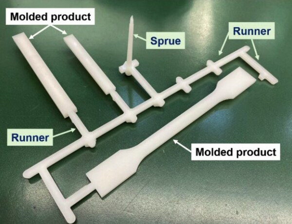
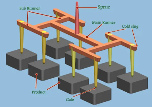
Runners are responsible for linking the sprue with each cavity within the mold. Their job is to direct the molten material so that it flows evenly into all cavities. Runner system is generally divided into two types: hot runner system and cold runner system. In creating runners, one must design them in such a way that material reaches every cavity without cooling off too much or losing pressure along the route. Its basic features — main runner(s), sub-runners1 and gates — should avoid subjecting the plastic to unnecessary temperature changes or drops in pressure. The layout, shape and dimensions of these channels will directly affect how the material behaves as it moves along them; therefore what we ultimately produce can also be affected by this choice.
What are the Functions of Gates and Runners?
Gates control the entry point of plastic into the mold, while runners connect the gate to the mold cavities. Their design impacts flow efficiency, cooling time, and part quality. Properly designed gates and runners minimize waste, reduce cycle times, and improve consistency in molded parts.
Functions of the Sprue
Connecting Function: The sprue links the nozzle of an injection-moulding2machine to its runner system, being the only pathway through which plastic can flow as it enters the mould. This connection guarantees a seamless shift for melted plastic from machine to mold.
Guiding Function: It directs the hot liquid plastic from the nozzle of the injection machine into the runner system. The sprue design must encourage even flow of plastic, so that air bubbles and turbulence are avoided.
Pressure Transmission: In order to achieve thorough filling, this system conveys the force from the injection unit to the mold cavity consists. Efficiency is directly influenced by how big around and long the sprue is: If it is too little, force dissipates, if it is too large, excess material will be generated.
Facilitates Demolding: The design of the sprue typically takes into account how easy it will be to remove the molded plastic part without causing damage or leaving material behind. Both the draft angle3 and the surface finish on a sprue can have a major impact on this process.
Functions of the Runner
Distributing Plastic: The runner system equally distributes plastic into every cavity so that each one fills consistently. The design and dimensions of the runners must allow for how the plastic flows, to keep its movement regular throughout the process.
Controlling Flow: By designing the runner, it becomes possible to control both the speed and path taken by the plastic—thus preventing such problems as uneven cooling and filling. The aim of runner design should be to cut down on pressure loss while also making sure no dead zones occur.
Reducing Waste: A well-designed runner can reduce plastic waste, increasing material utilization. Optimizing runner layout and size can reduce the volume of the runner section, thereby lowering production costs.
Reducing Pressure Loss: To minimize pressure loss while molten plastic flows through it — thus allowing for smooth filling — the runner system needs to be designed in such a way that both its cross-sectional shape and the finish on its surface help reduce flow resistance.
What are the Design Principles of Gates and Runners?
Gates control the entry of plastic into the mold cavity, while runners facilitate the flow of material. Properly designed gates and runners enhance filling efficiency, minimize material waste, and ensure uniform part cooling. Key design principles include optimizing gate location, runner size, and minimizing turbulence to improve cycle times and product consistency.
Design Principles of Sprues
Size and Shape: The sprue\’s dimensions and shape must be suitable for the flow properties of the molten plastic; it is usually designed with a cone shape to lessen resistance and help parts fall free more easily. Both diameter and length need careful adjustment depending on the plastic\’s own viscosity and how it flows as a melt.
Location: The sprue should be positioned as close to the injection molding machine nozzle as possible to reduce the flow distance and pressure loss of the molten plastic. The location should also facilitate mold installation and operation, avoiding interference with other parts of the mold.
Cooling System: It is essential to have suitable cooling systems close to the sprue. These systems will help maintain the plastic at the correct temperature as it moves into the runner. Cooling also needs to be evenly distributed so that the material cools uniformly; otherwise you may get flow problems either because solidification occurs too soon or unevenly along sections nearest gate (sprue).
Draft Angle: To prevent damage, it is important to incorporate an appropriate draft angle when designing the sprue so that it does not get harmed too easily during demolding. Usually, a draft angle ranging from 1 to 3 degrees for the sprue will allow for easy removal of the piece.
Product and Material: The requirements for product geometry, wall thickness, dimensions, stability, features and external quality. Plastic types, fluidity, melting temperature, solidify temperature and shrinkage.
Design Principles of Runners
Runner Shape: Runners are often made with a circular or trapezoidal cross-section in order to lower flow resistance of the molten plastic. Circular runners offer lowest flow resistance but are hardest to deal with; trapezoidal runners offer a balance between flow properties and processing convenience.
Runner Size: Runner Size should be determined by flow properties of the plastic, pressure and flow rate of the injection molding machine to allow smooth plastic flow. Calculate runner width & depth accurately for desired flow properties with minimal material waste.
Runner Layout: The runner layout should ensure that the plastic is distributed evenly to each cavity, avoiding uneven filling. The layout and design of runners should aim to reduce the length of the flow path and ensure uniform pressure distribution.
Cooling and Heating: In order to keep the plastic at the right temperature while it is flowing, it will be necessary to incorporate some method of heating or cooling into the runner system3. The design of the cooling system should ensure even cooling to prevent overheating or undercooling in parts of the runner.
What are the Common Problems and Solutions of Gates and Runners?
Common problems with gates and runners include incomplete filling, material drooling, and excessive pressure drops. Solutions often involve optimizing gate size and placement, adjusting processing conditions, and using appropriate runner designs to ensure consistent flow. Proper management can lead to enhanced cycle times and improved product quality.
Common Sprue Issues
Blockage: Blockage in the sprue can prevent the plastic from entering the runner smoothly, affecting molding quality. Solutions include increasing the sprue size, increasing injection pressure, and cleaning the sprue. Blockages may be caused by impurities or cold material in the plastic, so you should inspect and clean the sprue regularly.
Difficult Demolding: Difficult demolding may be due to poor design or strong plastic adhesion. Solutions include optimizing the sprue shape, increasing the draft angle, and using mold release agents. Difficult demolding may also be caused by a rough surface of the sprue, requiring polishing.
Uneven Cooling: If the sprue cools unevenly, it causes unstable plastic flow. Optimise either design of cooling system, cooling time or temperature. Uneven cooling may also be due to an inadequate cooling system design, requiring redesign and optimization.
Common Runner Issues
Uneven Flow: If the design of runners is not optimal, it may cause irregular plastic flow, which in turn can affect how well the cavity gets filled. Ways to deal with this iinclude fine-tuning the runner size and shape as well as its layout. Another possible reason behind uneven flows are varying cross-sections that need – therefore their runners must be machined exactly right.
High Pressure Loss: If runners are long or thin, there may be a high-pressure drop as the plastic flows – and this can affect the quality of moulding carried out. One solution is to shorten runners and make them broader; another is to increase their cross-sectional area. Losses attributed to rough surfaces might necessitate a polish.
Poor Cooling: When the runner system does not cool properly, the plastic may overheat or not cool enough while flowing – both of which can hurt quality. To fix this, molders can tweak cooling times and temperatures as well as how these channels are cooled; they might also need new design that works better overall at taking heat out of melted plastics.
What are the Optimization Methods and Case Studies for Gates and Runners?
Effective optimization methods for gates and runners involve analyzing flow patterns, adjusting gate sizes, and employing simulation software to predict outcomes. Successful case studies illustrate how companies improved cycle times and reduced defects by implementing these strategies, particularly in automotive and consumer product sectors. Key advantages include enhanced material utilization and consistent part characteristics.
Optimization Methods for Sprues
Optimizing Size: Find the best sprue size by experimenting and simulating to guarantee smooth plastic flow. Think about plastic flow features including pressure and flow rate from machine; then use this information along with an understanding of what makes for good design when deciding upon both lengths or diameters in order achieve optimal results.
Shape Optimization: This helps cut flow resistance plus makes demolding4 easier. You’ll also need to think about stability during plastic flow (which means considering tapers) as well as making sure there are no unnecessary snags when you take out your new object from its mould.
Location Optimization: Selecting the right spot for the sprue so as to decrease both flow distance and pressure loss suffered by molten plastic. When optimizing location, one must think about mold structure and production process–making sure that although sprue placement allows unobstructed movement of plastic, it doesn’t get in way with other mold parts.
Cooling System Optimization: Design a proper cooling system around the sprue to maintain temperature control during plastic flow. Cooling system optimization needs to consider the layout and size of the cooling channels, ensuring uniform cooling to prevent issues caused by poor cooling.
Optimization Methods for Runners
Runner Layout Optimization: Use simulation analysis and experiments to optimize runner system layouts so plastic is evenly distributed to every cavity. This means thinking about mould structure and production processes, layouts should be sensible in order for systems to have short flow paths with even flows.
Runner Cross-Section Optimization: Select the right shapes and sizes for runner cross-sections in order to minimize flow resistance and pressure loss. This optimization must account for both the fluid properties of the plastic being used and how well the injection molding machine can perform — meaning that widths and depths need to be designed within reason.
Flow Divider Optimization: Optimize the design of flow dividers to ensure uniform filling in multi-cavity molds. Flow divider optimization needs to consider the uniformity of plastic flow and the layout of the runner, ensuring even distribution of plastic to each cavity to avoid uneven filling.
Optimizing the Cooling System: Create the right heating or cooling elements for the runner system so plastic stays the ideal temperature while it flows. Cooling system optimization needs to consider the layout and size of the cooling channels, ensuring uniform cooling to prevent issues caused by overheating or undercooling.
Case Study
Below is a case study demonstrating the impact of optimizing sprue and runner design on injection molding process.
Case Background
A company producing plastic products using a multi-cavity mold encountered issues with uneven filling and defects in some cavities. Analysis revealed that the problems originated from the design of the sprue and runners.
Optimization Process
Sprue Optimization: After simulations and tests, they found that the sprue was too small. This caused high flow resistance. We increased the size of the optimized sprue and changed its shape to conical — which decreased flow resistance.
Runner Optimization: Our original design had a linear runner. This meant there was long path for plastic to flow through — and pressure loss along the way was high. They shaped runners like trapezoids instead (with flow channels inside them). Now pressure loss is reduced.Moreover, flow dividers have been added so that each part cavity receives an equal amount of plastic at all times.
Cooling System Optimization: The system now includes cooling elements around both the sprues and runners. Should temperatures rise too high during molding production, these elements automatically counteract this by lowering them again.
Optimization Results
After being optimized, the product’s filling effect got way better. Now each unit is filled evenly and overall quality has gone up by a lot. Not only that, but production efficiency went up too—plus there was less waste coming out of it meaning costs went down across-the-board!
Detailed Analysis
Before being optimized, the organization found major filling inconsistencies in the plastic items while they were being molded. This was causing bubbles and some cavities weren\’t filling completely. After doing a detailed analysis, they discovered this was because the sprue size was too small; there too much flow resistance; and runners were laid out incorrectly — all of which created both a long pathway for material to travel and an area where pressure was being lost along that route.
Through simulation analysis, the optimized sprue size was increased, and the shape was changed to a conical design, effectively reducing flow resistance. The runner design adopted a trapezoidal cross-section, reducing pressure loss. Flow dividers were added to ensure even distribution of plastic to each cavity. Cooling system optimization ensured temperature control during plastic flow, preventing flow issues caused by overheating or undercooling.
Finally, through these optimization measures, the company successfully resolved the uneven filling issue, significantly improved product quality, and enhanced production efficiency.
What is the Future Development Trend of Gates and Runners?
Future trends in gates and runners include advancements in 3D printing technology for creating custom designs, the use of lightweight and durable materials to reduce weight, and smart monitoring systems that enhance process control. These innovations aim to improve cycle times, reduce waste, and optimize material flow, ensuring higher quality products with less environmental impact.
Intelligent Manufacturing and Mold Design
Intelligent manufacturing advancements have led to smart design capabilities for sprues and runners. The use of computer-aided engineering (CAE) and computer-aided design (CAD) makes mold design more precise than ever before – streamlining the process significantly. Simulation analysis software allows mold flow analysis and optimization design before mold manufacturing5, identifying and resolving potential issues in advance.
Application of New Materials
As new and improved materials continue to emerge, injection molding specialists are increasingly turning to high-performance plastics. The only drawback is that when working with such novel substances, they need to make changes in how they design runners and sprues – alterations based specifically on what these materials can do. For a high-flow plastic there may be benefits in having smaller channels (that’s both sprues plus runners) so adjustments would need to be made there too. Conversely with some higher viscosity plastics it might be necessary not just have larger channels but more of them as well: again promoting an uninterrupted stream of liquid into the mould cavity!
Environmental Protection and Sustainable Development
Amid a growing focus on environmental preservation and sustainable progress, two key aims in mold design have gained prominence: cutting plastic waste and boosting material efficiency. Tweaking sprue and runner configuration is one way to achieve this when products are being made: doing so can curb the volume of unused plastic. Meanwhile, using more degradable plastics or renewable resources demands fresh thinking about how sprues and runners are shaped – because different materials flow at unlike rates through these channels.
High Precision and High Efficiency
In the future, mold design will emphasize increased precision and efficiency. One way to do this is by using more high-tech equipment and techniques during manufacturing. This can make sprues and runners more precise so that when things like plastic are pushed through them, less flow resistance occurs (which in turn lowers pressure loss). Another benefit of upgrading how molds are made includes boosting overall production speed along with finding ways to cut costs per item.
Conclusion
Sprues and runners are super important in plastic injection molding. If you design them right, you can make better parts, faster, and cheaper. When you design them, you have to think about how the plastic flows, how the mold works, and how the machine runs. You can use computer simulations and real-life tests to make sure your sprues and runners work the best.
By deeply understanding and optimizing sprues and runners, companies can gain an advantage in the competitive market, producing high-quality plastic products, meeting customer needs, and enhancing the company\’s core competitiveness. In the future, with the development of intelligent manufacturing, new material technologies, and the push for environmental protection and sustainable development, the design of sprues and runners will continue to progress, bringing more innovation and development opportunities to the plastic injection molding industry.
-
Learn about Understanding Mold Runners and Sub-Runners in Injection Molding: Sub-runners are smaller channels that connect the main runner to individual cavities. ↩
-
Learn about Injection Molding Nozzle – Types, Defects, And Characteristics Of A Quality Nozzle : An injection molding nozzle is a key part of the ejector system at the bottom of the molding machine. ↩
-
Learn about Draft Angle Guidelines for Injection Molding : Draft angle is the taper applied to the surface of a part. ↩ ↩
-
Learn about Demolding in Injection Molding: Techniques and Best Practices :Demolding is a critical step in the injection molding process where the finished part is removed from the mold cavity once it has solidified. ↩
-
Learn about What is Mold Manufacturing : A high-quality mold manufacturing process is essential to producing quality parts while maintaining a cost effective performance. ↩


