 Skip to content

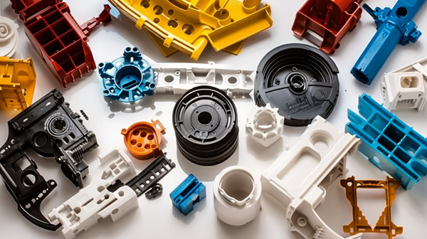
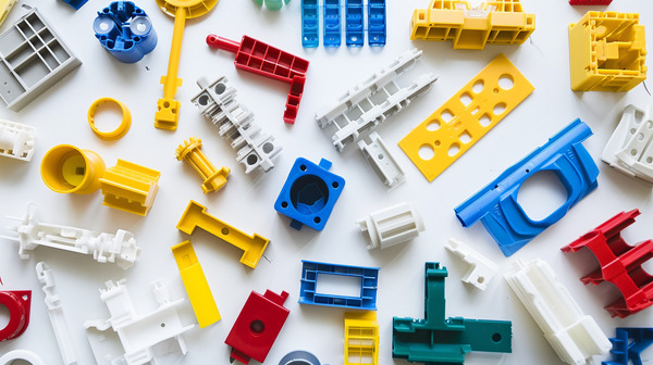
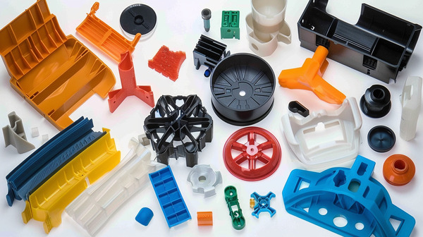
Introduction: Injection molding is the most common way to make plastic products that have multiple parts that need to be put together at the end. Putting parts together means making sure they fit right and stay together.
This is where tolerances come in. If you don’t say how much space there should be between parts, or if you don’t make sure the parts are the right size, the parts won’t fit together right.
Injection molding tolerances can be a pain in the neck because molds are expensive. So, you need to know how to control them.
In this article, I’ll explain what affects tolerances, and how to control them using design for manufacturing (DFM), material selection, tool design, and process control.
Why are Tolerances Important for Injection Molded Parts?
The amount of variation in any rapid prototyping process depends on its accuracy, and although injection molding is pretty accurate, there is still a little bit of variation.
This variation makes it important to figure out the range of allowable deviations for the parts to work right after you put them together.
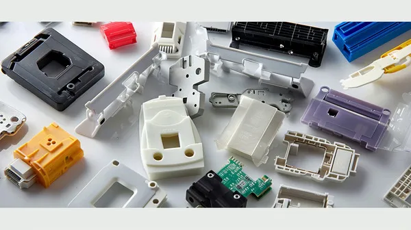
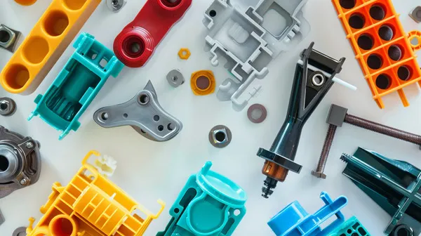
When you’re putting together a product that has multiple injection molded parts, you need to pay attention to the tolerances of the plastic molding.

Let’s say you want to connect two plastic molded parts together using bolts. You have to drill a hole in both parts.
If you make a mistake in the location and size of the hole, you’re going to have problems and lose functionality when you’re putting it together. So, both parts need positional tolerances to work right.
To put it simply, controlling and optimizing injection molding tolerances is like assuming the worst. It’s figuring out the range of acceptable deviations that will make your product work the best.
What Factors Influence Injection Molding Tolerances?
Part Design
One of the most important ways to limit warpage, excessive shrinkage, and part misalignment is to use DFM principles when designing your parts.
This is best accomplished by working with your injection molding service early in the design process to prevent costly redesigns later in the design phase.
Wall Thickness ; Parts with variable wall thickness can experience uneven shrinkage. When thick areas can’t be avoided, coring must be used to maintain uniform wall thickness. Uneven wall thickness can cause part distortion, which can affect tolerances and fit.
Thicker walls aren’t always the best choice for added strength; when possible, it’s best to use ribs and gussets to increase part strength.
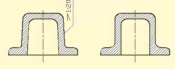
Draft Angle ; Draft angles are super important to make sure the part comes out of the tool easy.
If it’s not right, the part can get stuck when it’s coming out, scrape, and warp the finished product. Draft angles can be anywhere from 0.5° to 3°, depending on the part design and surface finish.
lBoss features ; Bosses are often used to accommodate fasteners when assembling multiple plastic parts. If the bosses are too thick, they may leave indentations on the part.
If they are not connected to the sidewalls by ribs, they may deform significantly. This will make assembly of these parts nearly impossible.
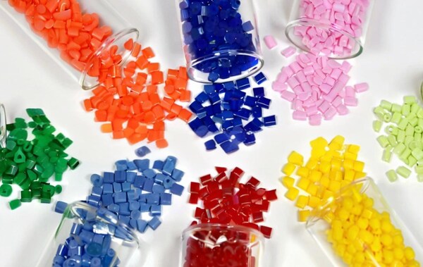
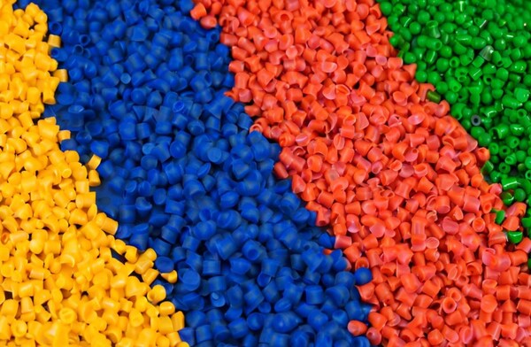
Material Selection
You can make injection molded plastics from a bunch of different resins. The ones you choose depend on what you’re making.
Each resin shrinks a different amount. When you design the mold, you have to account for this shrinkage. You usually make the mold bigger by the percentage the material shrinks.
If you’re making something with more than one kind of material, you have to design for different shrinkage rates.

If you don’t design the tolerances right, you can end up with parts that don’t fit together. That’s a big mistake in injection molding and it costs a lot of money.
Tolerances for injection molding are mainly determined by material shrinkage and part geometry.
You need to finalize material selection before you design and build the tool. The tool design is highly dependent on the material you choose.
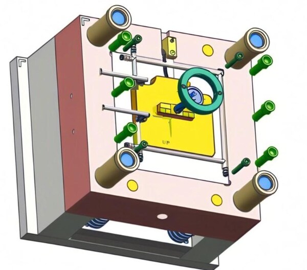
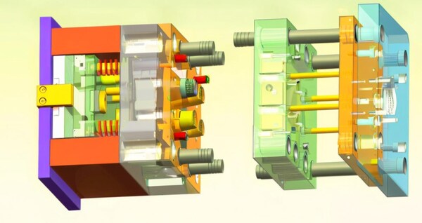
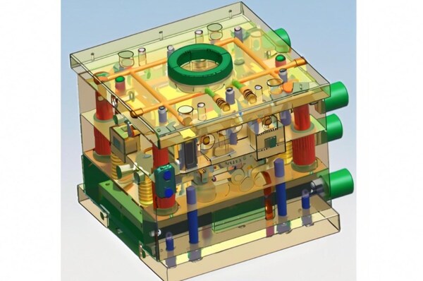
Tool Design
When you pick the material, you usually make the tool bigger to allow for the material shrinking. But the shrinkage isn’t the same in all directions. For example, thicker parts cool at different rates than thinner parts.
So, if you have a complex part with a mix of thin and thick walls, you’ll have different cooling rates.
That can cause the part to warp or sink, which can mess up the tolerances and fit of the injection molding. To help with that, the toolmakers think about these things when they design the mold features.
Cooling the tool; cooling the tool is important to make sure the part shrinks evenly. If the tool doesn’t cool right, the part will shrink unevenly and not be the right size. You can put water lines in the tool to help the part be the right size.
Tool tolerance is a big deal in injection molding because if a tool is out of tolerance, every part that comes out of that tool will have that error added to any error caused by shrinkage.
In CNC machining, tool tolerances are typically tightly controlled and monitored, so an out-of-tolerance tool is rarely the reason a part is out of tolerance.
In addition, these tools are typically “steel safe.” This means that when a tool is made, critical dimensions or features can be adjusted through additional milling.
If the finished dimensions of certain parts are not within tolerance, the additional material allows the tool to be fine-tuned through machining.
For example, a tight tolerance hole feature on a part may have a tool that has a core pin designed to be on the wider side of the tolerance. If the hole needs adjustment, it will be machined thinner to make the hole thinner.
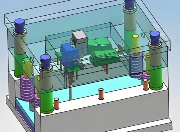
Ejector pin location; The ejector pin pushes it out of the mold as it opens; this needs to happen as quickly as possible to minimize cycle time.

If the ejector pin is placed in a less than ideal location, it can damage the part. Some materials are not completely rigid when they leave the tool, and uneven ejection can cause severe warpage and dimensional inconsistencies.
Gate location; The gate is where the resin goes into the tool. If you put it in the wrong place, it will look bad.
Also, if you don’t fill the mold evenly, the part will warp and shrink unevenly. Complex parts often need more than one gate to fill evenly and avoid these problems.
Process Control
Even if you do all the upfront design work and material considerations to optimize the injection molding tolerance of a part, it’s still possible that the part will be out of tolerance when the first samples are delivered.
Once you’ve done all of the above methods, the next step to improve tolerance compliance is to adjust the process.
Controlling temperature, pressure, and holding time are some of the most common ways to improve part quality.
Once you’ve figured out the ideal set of conditions, the mold can create consistent parts with very little dimensional variation between parts.
When you have a part with a lot of features, it’s a good idea to put pressure and temperature sensors in the tool so you can measure those things while you’re making the part.
That way, you can control the process and make sure you’re holding the tolerances. If you can keep the pressure and temperature in the tool all the time, you’ll have a much better chance of holding the tolerances.
When you have complex, multi-feature parts, it can be helpful to put pressure and temperature sensors in the tool to measure these parameters during the manufacturing process for real-time feedback and process control.
Keeping pressure and temperature in the tool at all times helps a lot to make sure you have consistent tolerances.
How to Optimize Injection Molding Tolerances?
To optimize injection molding tolerances, you can optimize product designs using design for manufacturing, using the right injection molding materials, adjusting injection mold design, and process control.
This section will cover each category so that you can achieve realistic plastic injection molding tolerances.
In the Design Phase
When manufacturers use injection molding, they run into problems like warpage, excessive part shrinkage, part misalignment, etc. during processing that affect the tolerances of injection molded parts.
To combat this, designers make sure that each product design follows the Design for Manufacturing (DFM) because it can limit the occurrence of such problems.
To get good DfM, you need to engage a good rapid prototyping service with extensive injection molding experience (like Rapid Direct) early in the design process.
Here are four things you should think about when it comes to part design.
Overall Size
The bigger the thing you’re making, the more you have to worry about tolerances. When you make something big in plastic injection molding, it can warp or shrink. So, you have to think about size.
Wall Thickness
Shrinkage is the shrinkage of a plastic part during the cooling phase. Shrinkage is an integral process in the injection molding process and is controlled by factors such as wall thickness, temperature, etc.
If you want to reduce cosmetic defects like warping, sinking, cracking, and distortion, you need to have a steady shrinkage rate.
And to have a steady shrinkage rate, you need to have uniform wall thickness. Here’s how you can get uniform wall thickness:
Don’t design parts with sharp inside corners, long unsupported spans, or poorly designed bosses. If you need to reinforce the walls, use ribs.
If you put radii on inside corners, it can help mitigate warping. Use the right material and consider wall thickness. Don’t use thick walls because they slow down cooling, which increases shrinkage and can cause warpage.

Draft Angles
Draft angles are a big deal in injection molding design because they make it easy to get the part out of the mold. Easy part removal means less friction, less wear, and a nice surface.

If you don’t think about draft angles when you’re injection molding, you’ll get shrinkage and parts will get stuck when you try to eject them (plastic materials like nylon still work great at 0).
Draft angles are measured in degrees/inches/mm, but there are no standard injection molding tolerance rules for incorporating them into your product design.
But we have some rules of thumb you can follow. A draft angle of 10 to 20 is good for most parts. Add 10 for 1 inch depth. Use 30 for light textures and >50 for heavy textures and use 0.50 on all vertical surfaces.
Bosses
Bosses are a big part of product design and are used to hold parts together when you put them together.
There are some important things to think about when you design bosses. One is that the walls of the boss can’t be too thick. If you put a thick boss in your design, here’s what will happen:
Voids and sink marks are created when you don’t core the bosses. This will extend your cycle time. You’ll also get plastic cracking during fastening.
In addition, you should core the bosses (i.e., connect them to the nearest sidewall). Doing so will result in additional load distribution on the part and improve part coolness and material flow.
Choosing the Right Material for Tight Injection Tolerances
Material selection is a big deal when it comes to injection molding tolerances because the material shrinks uniformly (i.e., injection molding materials shrink during the cooling phase due to density changes).
Shrinkage depends on factors such as wall thickness, temperature, part, and material type. When it comes to material selection, use the following factors to help you choose:
Plastic composition: ABS shrinks less than polyethylene because it’s less dense.
Molecular weight: High molecular weight resins have high viscosity and high pressure drop, which increases shrinkage.
Additives: Adding low thermal expansion fillers will reduce shrinkage.
Different resins shrink at different rates. So, you gotta keep this in mind when you’re picking materials and designing your injection mold.
This will help you reduce the cosmetic defects that mess with the tolerance of your injection molded parts. Stuff like warping, sinking, cracking, and distortion.

Keep Mold Tools in Mind
When you’re picking the right material, mold designers will tell you to increase the mold size to account for material shrinkage. Different materials shrink at different rates because of uneven thickness. To minimize this, keep the following in mind when designing the mold.
Tool Cooling
Cooling is a big deal in injection molding. It’s what makes the difference between a good part and a bad part. It’s the process of cooling down the hot plastic after it’s been injected.
Cooling needs to be even because if it’s not, you’ll get shrinkage, sink marks, ejection problems, warpage, and all kinds of other problems that will affect the appearance, the tolerance, and the function of the part.
To get even cooling, you need to put cooling lines in the mold in the right places. You also need to watch things like injection pressure, resin viscosity, and fill time.
Tool Tolerances
Injection molds are usually made using CNC machining. This allows for tight tolerances, which means the mold will stay accurate as it heats and cools.
The tolerances will make sure the part cools right without losing accuracy. But if you don’t control tolerances when you make the mold, you can get big defects like warping, shrinkage, sinking, and so on.
Ejector Pin Position
An ejector pin is a feature in an injection mold that pushes the final product out of the mold. The pin comes in different shapes (preferably flat) through which a certain force is applied to push the product out.
Therefore, when it is in the wrong position, it may cause unwanted indentations on the finished product. Moreover, in non-rigid materials or materials that cool unevenly, the ejector pin can crack the unfinished product, resulting in multiple cosmetic defects and physical distortions.
Gate Position
The gate is where the plastic goes into the mold. Put the gate where the part is the thickest. This will help the part not sink or have holes. It will also help the plastic flow better.
Put the gate where the part is the thickest so the part fills all the way. Don’t put the gate next to things like pins and cores.

Don’t let the gate mess up how the runner looks or how the part looks. The gate has to be in the right place. If the gate is in the wrong place, the part will not fill right. This will make the part warp and shrink and look bad.
Perform Repeatable Process Control
The manufacturing process has a lot of things that can affect the part being made, and process control is a way to make sure that all of those things are set up right so that the part comes out the way it’s supposed to.
Pressure and temperature sensors that are built into the mold tool are often a big part of getting good process control because they tell you what’s going on with those things in real time, so you can make changes fast if something bad is happening.
Once you have those things under control and you can do them the same way every time, the mold tool will be able to make parts that are the right size and that don’t change much.
Plastic resins usually have a higher coefficient of thermal expansion, which means they are more likely to change dimensions when the temperature changes.
So, parts with tighter tolerances often need to be measured at the same temperature to make sure they stay the same size and work right.

What are Achievable Maintain Injection Molding Tolerances?
To get real standard injection molding tolerances , you can put some doable plastic injection molding tolerances into the plastic mold design. Here are the common ones for the major plastics used in plastic injection molding:
Dimensional Tolerances +/- mm
Accuracy can be a real pain. That’s why designers use the (+/-) symbol to show the range of measurements. Every material has a different tolerance range as the size gets bigger. The table above shows the dimensional tolerances for the major plastics used for injection molding.
Straightness/Flatness Tolerances
Warp happens because the plastic shrinks differently in the direction of flow and across the flow. It can happen because different parts of the part have different wall thicknesses, which shrink differently.

You can minimize warp by changing the mold design, putting the gate in a better place, and controlling the process better. But you may have to have a realistic tolerance on the plastic side, because warp is hard to get rid of 100%.
Aperture Tolerances +/- mm
The bigger the hole, the more you have to worry about. The picture above shows you how much you have to worry about for different size holes.
Blind Hole Depth Tolerances +/- mm
Blind holes are holes drilled in the workpiece using an insert core that does not go all the way through the workpiece.
Blind holes are fixed and held at one end, which makes them more likely to deform under strong melt flow forces. The table above shows the different tolerances you can use.
Concentricity/Ovality Tolerance +/- mm
This is about figuring out the wall thickness (the difference between the outside and inside diameters). The picture above shows the different tolerances and cost differences to get this tolerance.
Conclusion
There’s always some variation in the injection molding process, so you need to have a range of allowable deviations so the parts work when you put them together.
That’s why injection molding tolerances are so important when you’re assembling products with multiple injection molded parts.
When you control and optimize injection molding tolerances, you can figure out the range of allowable deviations that will help your product work the best it can.
The most common ways to do this are mostly about DfM, material selection, and process control, and this injection molding tolerance guidelines can help you simplify the most common ways that will be really useful for your project . If you have any injection molding project, please feel free to contact Zetar Mold.
In summary, optimizing injection molding tolerances is important to make sure you can make your product efficiently and cost-effectively.
You do this by figuring out what tolerances you need, picking the right materials and processes, and adjusting your mold design and parameters.


