 Skip to content

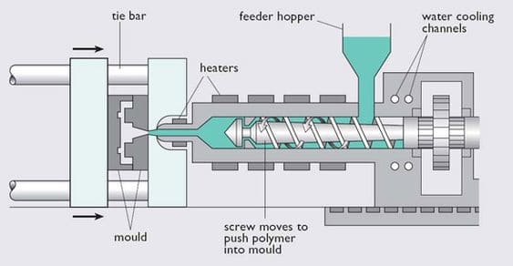
Injection molding is a manufacturing process that produces parts from thermoplastic and thermoset polymers. Injection molding is used to manufacture a wide variety of products, including medical devices, automotive parts, and consumer products.
To produce high-quality parts using the injection molding process, it is important to understand the basics of structural design. In this guide, we will discuss the principles of structural design and how they apply to plastic injection molded parts.
Plastics, along with steel, cement, and wood, are known as the four major engineering materials. With the progress of science and technology, the application of plastics has become more and more extensive. Engineers and technicians engaged in mechanical design should have some knowledge of the design of plastic components.
This blog summarizes several points of the structural design of plastic parts for the injection molding cycle, which can be useful for designing related products.
Reasonable wall thickness
From the perspective of injection molding quality, The material injected into the mold from the injection molding machine is cooled from a molten liquid to a solid. The wall thickness of plastic parts is too large, easy to produce defects such as depression and shrinkage in the molding process; it is too small and will cause difficulties in feeding glue, not easy to fill the cavity and cause lack of material.
Wall thickness of plastic parts should be as uniform as possible, can take the form of gentle transition, can also use the structure of local hollowing, so that the wall thickness becomes uniform, to avoid warping deformation and other defects in the molding process.
Wall thickness design
The size of the wall thickness depends on the external force that the product needs to withstand, whether it is used as a support for other parts, the number of pillar positions, the number of protruding parts, and the plastic material chosen.
In general, the wall thickness of thermoplastic should be designed to be 4mm. From the economic point of view, too thick products not only increase the cost of materials but also extend the production cycle “cooling time, increase production costs.
From a product design point of view, a thicker product increases the possibility of cavities and porosity, which greatly reduces the rigidity and strength of the product.
The ideal wall thickness distribution is undoubtedly a uniform thickness at all points of the cut, but variations in wall thickness to meet functional requirements are always inevitable.
In this case, the transition from thick to thin rubber should be as smooth as possible. Too abrupt a transition in wall thickness can lead to dimensional instability and surface problems due to differential cooling rates and turbulence.
For thermoplastics in general, when the shrinkage factor (is below 0.01mm/mm, the product can allow the thickness change up to; but when the shrinkage rate is higher than 0.01mm/mm, the product wall thickness change should not exceed).
For thermoset plastics in general, too thin product thickness often leads to overheating of the product during operation, resulting in scrap parts. In addition, fiber-filled thermosets tend to have the insufficient filler at too thin a location.
However, some easily flowable thermoset plastics such as Epoxy Epoxies can be as thin as 0.25mm if the thickness is uniform.
In addition, when using the production method of curing molding, the runners, gates, and parts should be designed so that the plastic flows from where the thick rubber is to where the thin rubber is.
This allows for proper pressure in the cavity to reduce shrinkage in the thicker areas and to avoid incomplete filling of the cavity.If the flow direction of the plastic is from the thin part to the thick part, structural foam production should be used to reduce the cavity pressure.
Flatness Guidelines
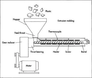
In most hot melt operations, including extrusion and cure molding, uniform wall thickness is very important.
Thicker glues cool more slowly than thin glues next to them, and shrinkage marks appear on the surface of the joint after the gate has solidified.
This can lead to shrinkage marks, thermal stress, distortion of the flexure, and different colors or transparency.
If a gradual change from thick to thin glue is unavoidable, the design should be as gradual as possible and within a wall thickness ratio of 3:1. The following diagram can be used for reference.
Corner guidelines
The same rule of uniform wall thickness is needed in the corners to avoid inconsistent cooling time. Longer cooling times will result in shrinkage, which will cause distortion and flexing of the part.
In addition, sharply rounded corners often lead to defects and stress concentrations in the part, and sharp corners often cause undesired material buildup after the plating process.
Areas of concentrated stress can break under load or impact. Larger rounded corners provide a solution to this drawback, not only reducing the stress concentration factor but also allowing for a smoother flow of plastic and easier release of the finished part.
The corner design guidelines also apply to the overhanging beam clamping position. Because this fastening method is required to bend the cantilever arm embedded, the design of the corner position illustrates that if the corner arc position R is too small will lead to its stress concentration factor (Stress Concentration Factor) is too large, therefore, the product bending when easy to break, arc position R is too large, then easy to appear shrinkage parting lines and hollow.
Therefore, the arc position and wall thickness are a certain ratio. Generally, between to, the ideal value is around.
Wall thickness limitation
Different plastic materials have different flowability. Where the glue level is too thick there will be shrinkage and where the glue level is too thin the plastic will not flow through easily. Here are some recommended adhesive thicknesses for reference.
Glue thickness design for thermoset plastics
Most of the thicker designs can be eliminated by using reinforcement and changing the shape of the cross-section.
In addition to reducing material and thus production costs, the eliminated design retains similar rigidity, strength, and functionality as the original design.
Design points for wall thickness of different materials
ABS
a) Wall Thickness
Wall thickness is the first consideration in product design and is generally in the range of 1.5 mm (0.06 in) to 4.5 mm (0.18 in) for injection molding.
Wall thicknesses smaller than this range are used for short plastic processes and small parts. Typical wall thicknesses are around 2.5 mm (0.1 in). In general, the larger the part, the thicker the wall thickness, which enhances part strength and plastic filling.
Wall thicknesses in the range of 3.8mm (0.15 in) to 6.4mm (0.25 in) are available with structural foams.
b) Rounded Corners
The recommended minimum fillet radius is 25% of the plastic thickness, with the most appropriate radius being 60% of the plastic thickness, a slight increase in radius can significantly reduce stress.
PC
a) Wall thickness
Wall thickness is largely determined by load requirements, internal stresses, geometry, external shape, plastic flow, injectability, and economics.
The recommended maximum wall thickness for a PC is 9.5 mm (0.375 in). For good results, the wall thickness should be no more than 3.1 mm (0.125 in). Ribs and some reinforcement structures can provide the same result where increased wall thickness is required for strength enhancement.
The minimum wall thickness for most PC applications is around 0.75 mm (0.03 in), with thinner areas depending on the geometry and size of the part. Short plastic processes are possible up to 0.3 mm (0.012 in) wall thickness.
The transition from thicker to thinner wall thicknesses is as smooth as possible. In all cases, the plastic enters the cavity from the thickest part to avoid shrinkage and internal stress.
Uniform wall thickness is very important. It is also important to achieve this requirement regardless of the corner of the plane, to reduce the problem of deformation after molding.
LCP
a) Wall thickness
Due to the high fluidity of liquid crystal copolymer under high shear, the wall thickness will be thinner than other plastics. The thinnest can be 0.4mm, and the general thickness is about 1.5mm.
PS
a) Wall thickness
The general design thickness of the rubber should not exceed 4mm, too thick will lead to a longer production cycle. It requires a longer cooling time and the plastic shrinks with a hollow phenomenon and reduces the physical properties of the part.
A uniform wall thickness is ideal for design purposes, but when there is a need to shift the thickness, the stress concentration in the transition zone should be removed. If the shrinkage rate is below, the wall thickness can be changed. If the shrinkage rate is above, only the change should be.
b) Rounded corners
An injection molded part needs to come out of the mold without damage or too much resistance. To avoid these issues, the walls of the part from the parting line (drafting). The design of the right angle is to avoid.
Right angles are like a node and can lead to stress concentrations that reduce the impact strength. The radius of rounded corners should be 25% to 75% of the wall thickness, generally recommended to be around 50%.
PA
a) Wall thickness
Plastic parts of nylon should be designed with the minimum thickness required for the structure. This thickness allows for the most economical use of the material. Wall thicknesses should be as uniform as possible to eliminate post-molding deformation. If the wall thickness transitions from thick to thin plastic, a gradual thinning process is required.
b) Rounded corners
The recommended rounding R-value is at least 0.5 mm (0.02 in), which is generally acceptable but try to use a larger R-value if possible. Because the value of the stress concentration factor decreases by 50% due to the increase in R/T ratio, and the best rounding angle is between R/T.
PSU
a) Wall thickness
The minimum wall thickness should be 2.3mm (0.09in) for large and long flow distances. Smaller parts can have a minimum of 0.8 mm (0.03in) and the flow distance should not exceed 76.2 mm (3 in).
PBT
a) Wall thickness
Maintain uniform wall thickness is a factor in the cost of the product. The thin wall thickness depends on the characteristics of each plastic. It is advisable to know the flow length limitations of the plastic being used before designing to determine wall thickness.
Load requirements often determine wall thickness, while other factors such as internal stresses, part geometry, inhomogeneities, and shape. Typical wall thicknesses range from 0.76mm to 3.2mm to 0.125in).
The wall thickness is required to be uniform, and if there is a thick or thin rubber area, the transition from the thick area to the thin area is gradual with a 3:1 cone bar ratio.
b) Rounded corners
The most common phenomenon of damage to parts is caused by sharp corners, increasing rounded corners is one of the methods to strengthen the structure of plastic parts. If the stress is reduced by 5% (from 3 to 3), then the ratio of rounded corners to wall thickness increases from to. This is the optimal performance recommended.

Column ( Boss )
Basic Design Guidelines for Bosses
Bosses are designed to protrude from the wall thickness of the rubber for assembling products, separating objects, and supporting other parts. Hollow pillars can be used to insert parts, tighten screws, etc. These applications must be strong enough to support pressure without breaking.
Struts should not be used alone but should be attached to the outer wall or used with reinforcement as much as possible, to strengthen the strut and allow for a smooth flow of adhesive.
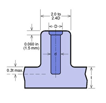
In addition, the height of the pillar should not exceed two and a half times the diameter of the pillar, because too high a pillar can cause air trapping when molding plastic parts.
In addition to the use of reinforcement bars, triangular reinforcement plates are also commonly used to strengthen the column, especially for columns away from the outer wall.
A good quality screw/pillar design combination depends on the mechanical characteristics of the screw and the design of the pillar hole.
Therefore, from the assembly point of view, it is necessary to partially increase the thickness of the rubber. However, this can lead to undesirable effects such as the formation of shrinkage marks, sink marks, cavities, or increased internal stresses.
For this reason, the location of the introduction and perforation holes of the pillar should be kept at a distance from the outer wall of the product. The latter not only increases the strength of the strut to support greater torsional and bending forces but also helps to fill the glue and reduce scorching due to air trapping.
For the same reason, pillars away from the outer wall should also be supplemented with triangular reinforcement blocks, which are particularly useful for improving the flow of glue in thin-walled pillars.
Design points for different material pillars
ABS
Generally, it is sufficient to have a strut with an outer diameter twice the inner diameter. Sometimes this results in a pillar wall thickness equal to or exceeding the thickness of the adhesive, which increases the material weight and creates shrinkage patterns and high molding stresses on the surface.
Strictly speaking, the thickness of the strut should be 50-70% of the thickness of the adhesive. If this design is used, the strut does not provide sufficient strength, but the surface shrinkage is improved.
Beveled bones are available to strengthen the column and can be extended from the smallest dimension to 90% of the column height. If the column is located close to the sidewall, a rib can be used to interconnect the sidewall and column to support the column.
PBT
Pillars are commonly used in most cases for assembly on mechanisms such as screw-in, press-fit, and inlet assembly, where the pillar’s outer diameter is twice the inner bore diameter is strong enough.
The pillar design is based on the concept of rib design. Too thick a cut will create external shrinkage of the part and internal vacuum. If the pillar is positioned next to the sidewall, the rib can be used to connect it, and the inner bore size can be increased to the maximum.
PC
Pillars are mostly used for assembling products, but sometimes they are used to support other objects or to separate objects. Even some very small pillars are eventually thermally dissolved and used to hold internal parts in place.
The side pillars need to be interlocked with some ribs to increase the strength of the pillar.
PS
Pillars are usually used for driving in parts, collecting screws, guide pins, tapping, or tight fits.
Whenever possible, avoid having a separate strut without any support. Some ribs should be added to strengthen it. If the column is not far from the sidewall, ribs should be used to connect the column to the side.
PSU
The pillar is used to connect two parts. The outer diameter should be twice the inner bore diameter and the height should not exceed twice the outer diameter.
Design principles of the reinforcement structure
Setting reinforcement on plastic parts can improve the strength and stiffness of plastic parts and prevent warping and deformation of plastic parts. Selecting the proper position of the reinforcement can improve the flow of the plastic melt.
The size of the reinforcement generally follows the following principles:
1.The wall thickness of the reinforcement is generally 0.4 times the thickness of the main body t, the maximum does not exceed 0.6 times;
2.The spacing between the bars is greater than 4t, and the height of the bars is less than 3t;
3.The reinforcement of the screw column is at least 1.0mm below the surface of the column;
4.Reinforcement bars should be at least 1.0mm below the surface of the part or parting surface.
Multiple reinforcement bars intersect, pay attention to the intersection of the local material buildup brought about by the problem
The improvement method is:
1. Misalignment of the reinforcement;
2. Design the intersection of reinforcing bars as a hollow structure.
Slender reinforcement, such as force, should try to make it withstand the tension, to avoid excessive pressure.
Because the plastic material has a very low modulus of elasticity, it is easy to have instability problems. This is contrary to the principle of preferential pressure that we follow in the design of metal castings and requires special attention.
Avoid stress concentration
The structural design of plastic parts should pay special attention to avoid the generation of sharp corners. The transition of the geometry at the corners is not continuous, and stress concentrations can occur here, which can lead to cracks.
The strength of plastic materials is usually very low, and stress concentrations are more likely to cause damage. The main measure to avoid stress concentrations is to improve the structural form of the sharp corners of the component. For example, adding chamfers, and rounded corners, or replacing them with gently sloping transition sections at sharp corners.
When chamfering and rounding cannot be added directly because of the function of the component, the stress concentration can be reduced by reducing the local structural strength at the sharp corners and hollowing out the rounded corners inward, referring to the improved design scheme of the linear guide shown in Figure 1.
The thread shape of plastic threads should preferably be round and trapezoidal, avoiding triangles and rectangles, which can reduce the gap effect and improve the bearing capacity of the threads.
Designing a suitable die slope
The mold pulling slope also called the mold release slope, is an angle set in the mold release direction to avoid the plastic parts from sticking and rubbing against the mold due to cooling shrinkage during mold release, thus causing damage and deformation.
Injection molded products are usually designed with an inclined angle on the inside and outside of the edge to allow the product to be easily released from the mold.
If the product has a vertical outer wall and is in the same direction as the mold opening, the mold will require a large opening force to open after the plastic has been molded, and it may be difficult to release the product from the mold when the mold is opened.
If the product has been molded with an exit angle and all mold parts in contact with the product are highly polished during the process, the release of the product from the mold will be a breeze.
Therefore, consideration of the exit angle is indispensable in the product design process.

The determination of die slope generally follows 3 principles
1. The angle of mold pulling is generally taken as a whole number, such as 0.5°, 1°, 1.5°, etc. (except for matte and nibble);
2. The appearance of the plastic parts to take the mold angle is greater than the angle of the inner wall, which is conducive to molding off the mold;
3. Take a larger angle without affecting the appearance of the mold. Certain materials, such as PP, PE, etc. can be forced to release the mold, the forced release amount generally does not exceed 5% of the maximum cross-sectional area of the core.
Size of die slope
There is no certain guideline for the size of the exit angle, it is mostly determined by experience and the depth of the product. In addition, the molding method, wall thickness, and choice of plastic are also taken into consideration.
In general, a 1/8 degree or 1/4 degree exit angle can be used for highly polished outer walls. Products with deep or woven patterns require a corresponding increase in the exit angle, customarily an additional 1 degree for every 0.025 mm of the weave.
The table showing the relationship between the exit angle and the single edge clearance and the edge depth can be used as a reference.
In addition, when the product requires long and deep ribs and small exit angles, the ejector pin design must have special treatment, see the ejector pin design for deep and long reinforcement.
Design points of the slope of the mold pulling for different materials
ABS
Gener, ally the application of side ° to 1 ° is sufficient. Sometimes the exit angle can be close to zero because the polishing pattern is in the same direction as the exit pattern.
For patterned sides, add 1° to the exit angle for every 0.025 mm (0.001 in) of depth. The correct exit angle can be obtained from the etching supplier.
LCP
Because of the high modulus and low ductility of liquid crystal copolymers, inverted buckling should be avoided in the design.
A minimum exit angle should be provided at all ribs, wall edges, pillars, etc. above the protruding glue level.
If the wall edge is deep or does not have a polished surface or etched pattern, additional above is required.
PBT
If the part has a good surface finish, a minimum release angle of 1/2° is required.
Etched surfaces require an additional 1° release angle for every 0.03 mm (0.001 in) of depth.
PC
The release angle is to be present on any side or projection of the part, including the upper and lower molded areas.
Generally, a glossy surface of 2° to 2° is sufficient, however, etched surfaces require an additional release angle of 1° for every 0.25mm (0.001 in) of depth.
PET
The ribs of plastic products, pillarsidewallss, runner walls, etc., such as its release angle can reach 1 ° is sufficient.
PS
PS release angle is extremely fine, and a 1° release angle is the standard method; too small a release angle makes it difficult to release the part from the mold cavity.
In any case, any release angle is better than no angle at all. If the part is etched, for example, the depth of the leather pattern, add 1° to the release angle for every 0.025 mm of depth.

Consider the structural design of plastic parts from the perspective of the mold structure
1. Too many complex structures should be avoided when designing the structure of plastic parts
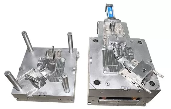
The process equipment for injection production is the mold, and the mold is a reflection of the shape of the injection molded part.
Due to the complex structure of plastic parts, the mold has to be complicated in structure, and even the structure that cannot be realized, the plastic parts should take this into full consideration when designing, and strive to make the injection mold structure as simple as possible under the premise of ensuring the appearance and function, to save time and cost and can improve product quality.
For example, there are a lot of side grooves and side holes on the plastic parts that prevent the products from exiting the mold in the ejection direction, so generally, we should take the structure of core extraction and inclined top.
If the recesses and side holes are designed to be consistent with the ejection direction or designed to touch through the structure, it will greatly simplify the mold structure under the premise of achieving the function and ensuring the appearance. Therefore, too many complicated structures should be avoided when designing the structure of plastic parts.
2. The design of plastic parts should avoid internal cutting structure
Plastic parts with internal cut structure can not be directly off the i mold, resulting in the mold can not be designed or must use the mold core, hidden structure, or will be separated from the mold, but this increases the complexity of mold making, reduces the reliability of the mold, the possibility of producing scrap increases, and increases the manufacturing cost. Therefore, the internal cutting structure should be avoided as much as possible when making the structural design.
3. The design of plastic parts sometimes must take the lateral release because of the appearance or assembly requirements
This requires that the design should fully consider the structure of the mold and the impact of the mold structure on the product itself.
a) The problem of slanting top and slider: Slanting top and slider, in the direction of mold separation and perpendicular to the direction of mold separation, have movement. Slant top and line bit in the direction perpendicular to the parting die can not have a rubber bit blocking the movement, to have enough space for movement.
b) Treatment of vertical surface: the appearance of some plastic parts requires that there can be no slope, to ensure that the sidewall is vertical, it is necessary to design the slider or slant top at the vertical surface.
Go slider with wiring, to avoid wiring obvious, generally, put the wiring at the intersection of the face and face, plastic parts design need to take into account the special characteristics of this location.
Design considering the non-isotropic characteristics of plastics
Sometimes plastics are not isotropic like metals, and in such cases, the direction should be in the same direction to avoid the shortcomings.
For example, for some plastics with reinforcement materials, the direction of the adhesive flow should be the same as the direction in which the member is carrying a larger load because the direction of the axis of the reinforcing fibers flowing with the molten plastic is the same as the direction of material flow.
A beam-like structure with reinforcement, which is made of plastic with reinforcing fibers, has its main load-bearing direction in the direction of the length of the reinforcement, so the correct direction of glue feeding should also be in the length direction.
When the member is glued in multiple points, the direction of force should be avoided to be parallel to the fusion line. Because the part where two or more glue streams meet, the decrease of glue temperature will cause the bonding strength to be lowered and the fracture will occur easily. The correct plastic injection molding design method is that the force direction is perpendicular to the melt line or at a certain angle.
Consider the structural design of plastic parts from the perspective of assembly
Due to the small modulus of elasticity of plastic material, i.e. the material is soft, and the molding process is different from that of metal parts, the tolerance accuracy of plastic parts is generally much lower than that of metal parts.
Therefore, attention should be paid to this characteristic when designing the structure, and the situation of large size and small tolerance should be avoided.
The larger the size, the greater the accumulated deformation of the component, and the greater the impact on tolerance accuracy. Bonding is one of the common assembly methods for plastic parts.
Plastic parts bonding should be avoided when the bonding interface should not be subjected to tearing tension, because of its poor tear resistance, the correct approach is to make the bonding interface subjected to shear force.
In the state of positive tension, the bonding strength is not as strong as in the state of shear bonding strength, because in the state of positive tension bonding interface is the root of the tearing tension; and in the state of shear bonding interface area is generally larger than the area of the bonding interface in the state of positive tension, so the tearing resistance is stronger.
Bolt connection is also one of the common assembly methods of plastic parts. Because the strength of plastic is very low, usually not enough to bite the screw, in the case of large forces, not directly embedded in the plastic self-tapping screws.
In addition, flat-head bolted or riveted connections should be made with a larger area liner to increase the force area.

Product Structure Design Guidelines – Snap Joints
Basic Design Guidelines for Snap Joints
Snap joints provide a convenient and economical method of product assembly because the combined parts of the snap joints are formed at the same time as the finished product is produced, and the assembly does not require the use of other fastening accessories such as screws and meshes, as long as the two sides of the snap joints that need to be combined are snapped together.
Although the design of the clasp can have a variety of geometric shapes, the principle of operation is generally the same: when two parts are clasped, the hook-shaped part of one part is pushed away by the flange part of the adjacent part until the flange part is finished.

The operation principle of buckling
The design of the fastener can be divided into two types, permanent and removable, as distinguished by function. The permanent type is easy to install but not easy to remove, while the detachable type is easy to install and remove.
The principle is that the hook-shaped part of the detachable fastener is equipped with appropriate import and export angles to facilitate the action of fastening and detaching, and the size of the import and export angles directly affects the strength required for fastening and detaching.
The permanent type of clasp has only the inlet angle but not the outlet angle, so once it is fastened, the connected parts will form a self-locking state and cannot be easily removed. Please refer to the schematic diagrams of permanent and removable fasteners.
Principle of permanent and detachable fasteners
If the shape of the buckle is used to differentiate, it can be broadly divided into the ring-type buckle, single side buckle, ball-type buckle, and so on.
The following is a list of the types of buckles.
Spherical buckle (detachable type)
The design of the buckle bit is generally inseparable from the method of the overhanging beam type, and the extension of the overhanging beam type is the ring type buckle or ball type buckle. The so-called overhanging beam type is the use of the plastic itself deflection deformation characteristics, after the elastic return to the original shape.
The design of the buckle is required to calculate, such as the assembly of the force, and after the assembly of the stress concentration of the gradual behavior, is to be considered from the plastic properties.
The commonly used buckle of suspension beam is constant cut, if you want the deformation of suspension beam to be bigger, you can use gradual cut, the thickness of one side can be gradually reduced to half of the original. Its deformation can be more than sixty percent more than the constant section.
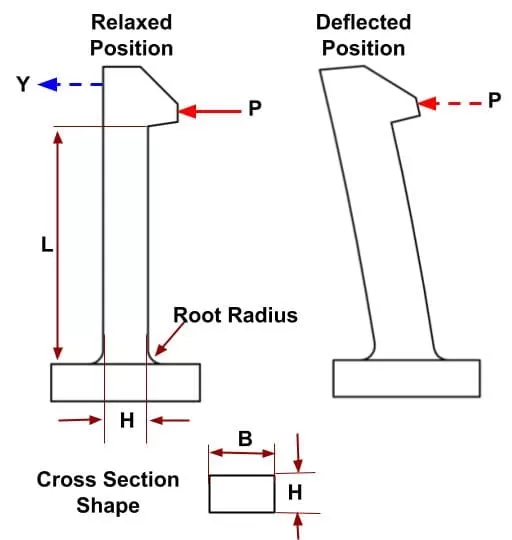
Comparison of the buckling and deformation of different forms of cut
The weakness of the fastening device is that the two combined parts of the fastening: the hook extension part and the flange part are prone to deformation and even fracture after repeated use, and the fractured fastening is difficult to repair.
Because the buckle and product are molding at the same time, so the damage to the buckle is also the damage to the product. The remedy is to design the buckle device to share multiple buckles at the same time, so that the overall device will not be unable to operate because of damage to individual buckles, thereby increasing its service life.
Another weakness of the buckle device is that the tolerance requirements of the buckle-related dimensions are very strict, too many buckle positions are easy to form the buckle damage; on the contrary, too few buckle positions are difficult to control the assembly position or the combination of parts appears toolset phenomenon.
Conclusion
This paper is only a summary of the problems commonly encountered and easily ignored in the design of plastic parts structure. Only by studying and summarizing in actual work and accumulating experience in practice can we design plastic parts with reasonable structure and excellent performance.


