 Skip to content

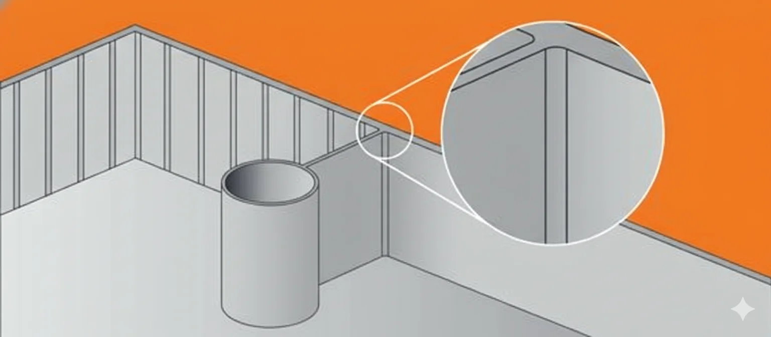
**Ribs** are thin, wall-like features integrated into plastic parts to add structural strength and stiffness without increasing overall wall thickness. The golden rule of rib design is to maintain a rib thickness of **40% to 60%** of the nominal wall thickness. Violating this ratio often leads to cosmetic defects like **sink marks**. Proper draft angles (0.5°–1.5°) and base radii are essential for mold ejection and stress reduction.
Definition: Plastic Ribs
In the context of Injection Molding, a Rib is a structural feature extending perpendicular to a wall or plane of a plastic part. Its primary function is to increase the bending stiffness (moment of inertia) of the component without adding significant weight or cycle time, which would occur if the entire wall thickness were increased.
Ribs are also used as flow leaders to assist molten plastic—such as Polypropylene (PP) or Acrylonitrile Butadiene Styrene (ABS)—in filling thin sections of the mold cavity.
Key Design Parameters and Guidelines
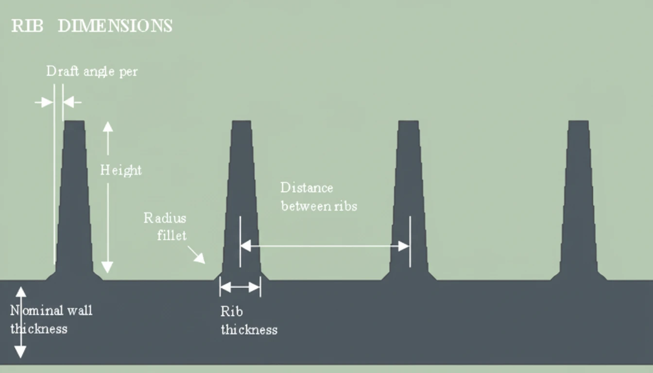
To prevent manufacturing defects, rib geometry must strictly adhere to specific ratios relative to the Nominal Wall Thickness (t).
| Parameter | Recommended Value / Range | Key Notes |
|---|---|---|
| Rib Thickness (w) | 40% – 60% of nominal wall (t) | Exceeding 60% increases the risk of sink marks1 on the visible surface (A-side). |
| Rib Height (h) | Max 3.0 × nominal wall (t) | Excessive height requires higher injection pressure and creates gas trap risks; deep ribs are hard to cool. |
| Draft Angle | 0.5° to 1.5° per side | Essential for ejection. Reduce draft only if the rib surface is textured or polished to a high grade. |
| Base Radius (Fillet) | 0.25 × nominal wall (t) | Minimum radius of 0.25mm is advised to reduce stress concentrations and improve flow. |
| Rib Spacing | Min 2.0 × nominal wall (t) | Spacing too closely creates "steel safe" areas in the mold that are difficult to cool (heat sinks). |
| Tip Thickness | Min 0.75 mm | Ensure the tip is thick enough to allow gas venting and prevent short shots. |
Rib thickness should be maintained between 40% and 60% of the adjacent wall thickness to prevent sink marks.True
Keeping the rib thinner than the wall minimizes the mass of material at the intersection, ensuring uniform cooling and preventing surface depressions.
Making ribs as thick as the main wall creates the strongest part with the best surface finish.False
Thick ribs create hot spots that cool slowly, causing the material to shrink inward and create visible sink marks on the opposite surface.
Advantages vs. Disadvantages
Using ribs effectively requires balancing structural needs against cosmetic requirements.
| Advantages | Disadvantages |
|---|---|
| Enhanced Stiffness: Increases rigidity significantly without thickening the entire part. | Sink Mark Risks: Improper thickness ratios (>60%) lead to visible surface depressions. |
| Material Savings: Uses less plastic resin than increasing global wall thickness. | Mold Complexity: Requires EDM (Electrical Discharge Machining) to cut deep rib slots in the mold tool. |
| Cycle Time Reduction: Thinner ribs cool faster than a thick solid wall would. | Ejection Issues: Deep ribs with insufficient draft can stick in the mold. |
| Warp Resistance: Properly placed ribs (e.g., cross-hatching) help maintain part flatness. | Stress Concentration: Sharp corners at the rib base can lead to part failure under load. |
Common Application Scenarios
- Electronics Enclosures: Reinforcing thin walls in laptop cases or remote controls made of Polycarbonate (PC) to pass drop tests.
- Automotive Trim: stiffening large, flat instrument panels or door liners to prevent flexibility and vibration.
- Consumer Packaging: Strengthening the rims and bases of thin-walled containers or crates.
- Structural Brackets: Supporting heavy loads in internal appliance components (e.g., washing machine gears).
- Gear Webs: Reducing mass in plastic gears while maintaining radial strength.
Step-by-Step Design Process
Follow this workflow to integrate ribs into your CAD design for optimal Design for Manufacturing (DFM)2.
- Establish Nominal Wall (t): Define the base wall thickness of your part (e.g., 3.0 mm).
- Calculate Rib Thickness (w): Multiply t by 0.5 (50%). Ideally, set rib thickness at the base to 1.5 mm.
- Determine Height: Ensure the rib is no taller than 3 × t (e.g., 9.0 mm). If more strength is needed, use multiple shorter ribs rather than one tall rib.
- Apply Draft: Add a draft angle of at least 0.5° to each side of the rib to facilitate part release.
- Add Fillets (Radii): Add a radius of 0.25 × t (e.g., 0.75 mm) at the base where the rib meets the wall to distribute stress.
- Check Spacing: If using multiple ribs, ensure the space between them is at least 2 × t (e.g., 6.0 mm) to allow for proper mold cooling channels.
Adding base radii (fillets) to ribs significantly reduces mechanical stress concentration and assists in material flow.True
Sharp corners act as stress risers where cracks begin; radii distribute load and help molten plastic flow smoothly into the rib feature.
Ribs should always be oriented parallel to the mold opening direction without any draft angle.False
While ribs are usually parallel to the draw, a draft angle is mandatory. Without draft, the vacuum effect and friction will cause the rib to stick in the mold during ejection.
FAQ: Injection Molding Rib Design
Q1: Why do ribs cause sink marks on the opposite side?
A1: Sink marks occur because the intersection of the rib and the wall contains more material mass. This area retains heat longer and cools slower. As it solidifies, it shrinks inward, pulling the surface down. Keeping ribs thin (<60% of wall) minimizes this mass.
Q2: Can I use ribs to replace solid wall thickness entirely?
A2: Yes, this is a core principle of "coring out." Instead of a solid 10mm block, designers use a 3mm shell with internal ribs. This reduces weight and cooling time while maintaining structural integrity.
Q3: What if I need a rib thicker than the recommended 60%?
A3: If structural analysis requires a thick rib, consider using Gas-Assist Injection Molding or structural foam molding. Alternatively, use a cosmetic plate or texture on the A-side to hide the inevitable sink marks.
Q4: How does material selection affect rib design?
A4: High-shrinkage materials like Polyethylene (PE) or Polyoxymethylene (POM) are more prone to sink marks and warping. For these materials, adhere strictly to the lower end of the thickness ratio (40%). Low-shrinkage amorphous materials like ABS/PC are slightly more forgiving.
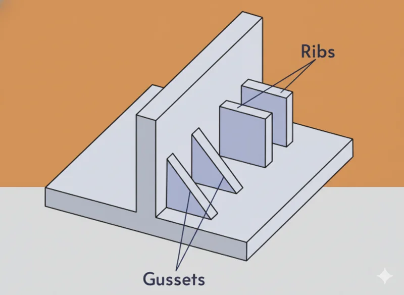
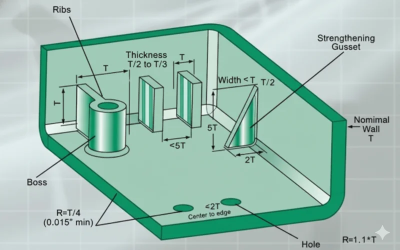
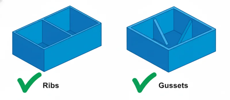
Q5: What is the difference between a rib and a gusset?
A5: A rib is generally a long, wall-like support. A gusset3 is a triangular support connecting a standing boss or wall to the floor, specifically used to prevent deflection in a localized area.
Summary
Mastering Plastic Rib Design is essential for creating lightweight, strong, and cost-effective injection molded parts. By strictly adhering to the 50% wall thickness rule, applying appropriate draft angles, and managing rib height, engineers can avoid common pitfalls like sink marks and warping. Always consult DFM guidelines early in the design phase to ensure your geometry is optimized for the molding process.
-
Protolabs Design Tips: This resource provides visual examples of sink marks and detailed calculations for rib-to-wall thickness ratios. ↩
-
Xometry Rib Guidelines: A comprehensive guide on standardizing rib geometry to reduce tooling costs and improve part quality. ↩
-
Fictiv Molding Guide: Explains the distinction between ribs, gussets, and bosses, offering practical strategies for structural reinforcement. ↩


