 Skip to content


Flow marks in injection molding can jeopardize product quality, requiring precise adjustments to ensure optimal surface finish and functionality.
Flow marks occur when varying plastic flow speeds affect the surface quality. To adjust, optimize processing parameters, refine mold design, and select suitable materials for improved consistency and aesthetics.
Understanding the causes of flow marks and the strategies for eliminating them can greatly enhance your production outcomes. Dive deeper to discover targeted solutions for addressing flow marks in injection molding processes.
Adjusting temperature and injection speed can reduce flow marks.True
Controlling these variables helps ensure consistent plastic flow, mitigating the risk of surface defects like flow marks.
Flow marks only affect the appearance of molded parts.False
While often a cosmetic issue, severe flow marks can indicate underlying problems that may impact the part’s structural integrity.
What are Flow Marks on Injection Molded Products?
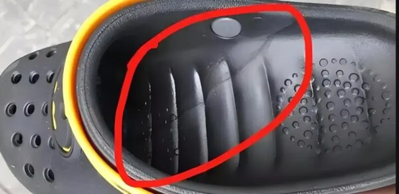
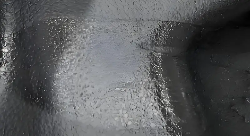
Flow marks occur on the surface of injection molded products, affecting aesthetics and potentially revealing underlying production issues.
Flow marks are surface imperfections on molded parts, resulting from variations in material flow during injection. Common causes include inconsistent cooling, inadequate mold design, and poor material selection. Identifying these issues is essential for manufacturers to improve product quality and appearance.

Flow marks are caused by the physical properties of the material, and the phenomenon is just as its name suggests. The flow traces of the material are called flow marks1, and the flow marks are basically caused by fillers in the material.
Of course, this filler includes masterbatches2. If the masterbatches are not colored well, granular color blocks will form. When flowing, it will flow like a river through areas with inconsistent thickness.
Flow marks only affect the appearance of molded parts.False
While primarily aesthetic, flow marks can indicate deeper issues in mold design or process parameters that may affect part functionality.
Proper mold design can completely eliminate flow marks.False
While improving mold design can reduce flow marks, other factors like material selection and processing conditions also play crucial roles.
Why do Flow Marks Appear in Injection Molding Machine Products?
Flow marks in injection molding products are visual defects often caused by differences in material flow and cooling, affecting both aesthetics and functionality.
Flow marks in injection molded products typically arise from variations in the material’s flow or cooling rates during the molding process. Key causes include inadequate mold design, inconsistent injection speeds, or improper temperature settings. Solutions involve optimizing mold design and processing parameters to enhance product quality.
Plastic
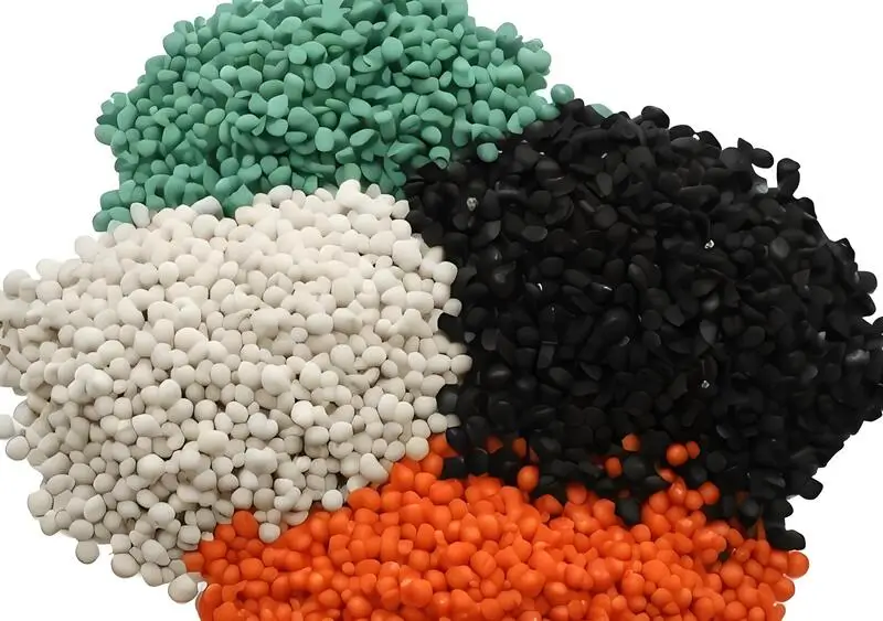
Plastic material is one of the key factors in injection molding. If the material is not right, it will cause flow mark problems.
Molds with a high flow length to wall thickness ratio (Flow Length to Thickness Ratio) need to be filled with a plastic that flows easily. If the plastic doesn’t flow well enough, the melt will flow slower and slower, and the slower it flows, the colder it gets.
The injection pressure and holding pressure aren’t enough to press the condensed skin tightly against the mold surface, so shrink marks are left in the flow direction of the melt.
When you use ABS or other copolymer resin raw materials, if the processing temperature is high, the volatile gases generated by the resin and lubricant will cause cloud-like wave flow marks on the surface of the plastic part.
The wear-resistant material has poor fluidity, which causes annual ring-shaped wave flow marks to form on the surface of the plastic part with the gate as the core.
When the ultra-low temperature and low viscosity wear-resistant material with poor fluidity is introduced into the concave mold in the injection port and flow channel in a semi-dry solid wave manner, the wear-resistant material flow along the surface of the mold core and is squeezed by the wear-resistant material continuously introduced behind, resulting in backflow and stagnation .
Thus causing annual ring-shaped wave flow marks to form on the surface of the plastic part with the gate as the core. Mold design is another biggie in injection molding. If the mold design3 is bad, the plastic won’t flow evenly in the mold, and you’ll get flow marks.
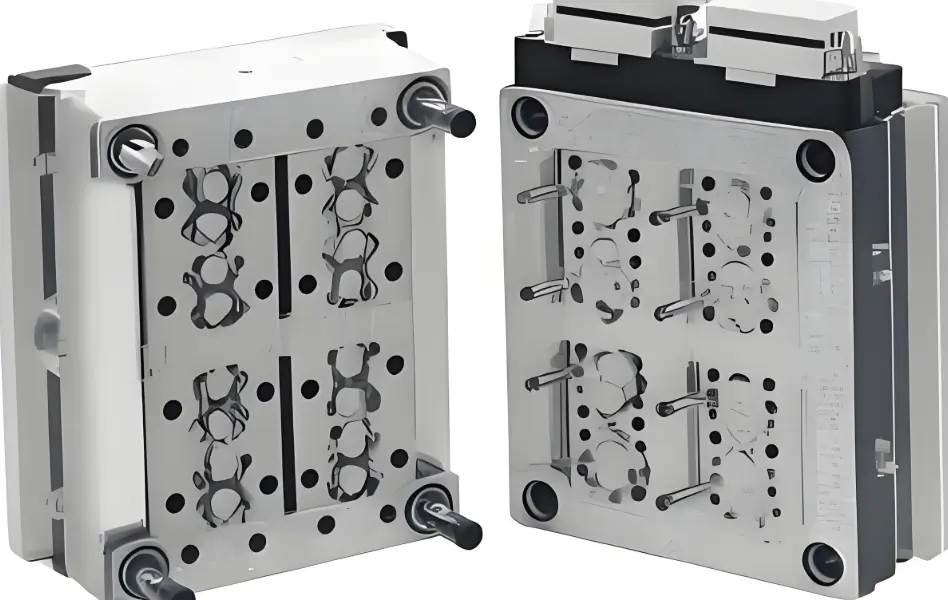
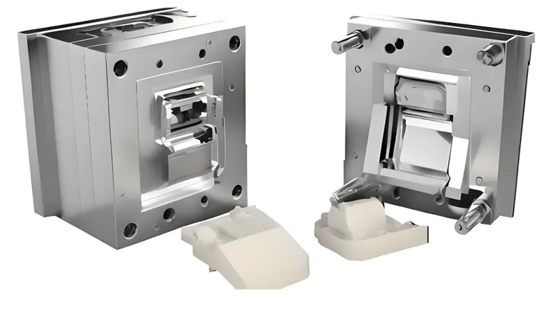
Mold
Mold design is another biggie in injection molding. If the mold design is bad, the plastic won’t flow evenly in the mold, and you’ll get flow marks.
If the mold temperature is too low, the material temperature will drop too fast, and the injection pressure and holding pressure will not be enough to press the condensed skin tightly against the mold surface, leaving shrinkage marks4 in the flow direction of the melt. If the mold temperature is too high, the plastic melt will stick to the mold surface and will not flow easily, thus forming flow marks.
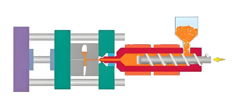
Injection Molding Machine
If you inject too fast, the plastic can’t push the air out of the way as it flows into the mold, and you get flow marks.
If you don’t have enough pressure, the plastic can’t fill the mold fast enough as it flows in, and you get flow marks.
Melting Material
When the melt flow is poor, you get these ring-shaped flow marks on the surface of the plastic part, right around the gate. When the melt is cold and thick and doesn’t flow well, it gets injected into the cavity in a half-solid wave state in the gate and runner.
It flows along the surface of the mold cavity and gets squeezed by the melt that comes in behind it, and it backs up and gets stuck, and that’s what makes these ring-shaped flow marks on the surface of the plastic part, right around the gate.
When the melt doesn’t flow well in the runner, it causes spiral wave flow marks on the surface of the plastic part. When the melt flows from a narrow runner section into a larger cross-section cavity or the mold runner is narrow and the finish is very poor, the flow is easy to form turbulence, resulting in spiral wave flow marks on the surface of the plastic part.
The injection pressure and holding pressure are not enough to press the condensed skin tightly against the mold surface, leaving shrinkage marks of the melt in the flow direction.
The plastic stays in the material tube for too short a time, and the melt temperature5 is low. Even if the cavity is barely filled, the plastic can’t be compacted during the holding pressure, leaving shrinkage marks in the flow direction of the melt.
When the cycle time is too short, the plastic doesn’t get heated in time in the material tube, and the melt temperature is low. Even if the cavity is barely filled, the plastic can’t get compacted during the holding pressure, leaving shrinkage marks in the flow direction of the melt.
When the temperature of the material tube is too low, the temperature of the melt is low, and the injection pressure and holding pressure are not enough to press the condensed surface tightly against the mold surface, leaving shrinkage marks in the flow direction of the melt.
The plastic absorbs the heat released by the heating bands and the friction heat generated by the relative movement of the plastic molecules caused by the rotation of the screw, and the temperature gradually rises. The last heating zone in the material tube is the nozzle. The melt should reach the ideal material temperature here, but it must be heated moderately to maintain the best state.
If the nozzle temperature isn’t set high enough, the nozzle and mold will be in contact, taking away too much heat, the material temperature will drop, and the injection pressure and holding pressure won’t be enough to press the condensed surface tightly against the mold surface, leaving shrinkage marks in the flow direction of the melt.
Flow marks are an inevitable part of injection molding.False
Proper optimization of mold design and processing parameters can prevent flow marks in many cases.
Inconsistent cooling can lead to flow marks in injection molded products.True
Uneven cooling can cause variations in the material flow, resulting in visible lines or patterns on the product surface.
What are the Solutions for Flow Marks on Injection Molding Machine Products?
Flow marks are a common defect in injection molding that can compromise product appearance and quality, but effective solutions can minimize their occurrence.
Flow marks, often caused by irregular flow of molten plastic, can be mitigated by optimizing injection speed, temperature, and mold design. Solutions include adjusting process parameters and using mold flow analysis tools to enhance product aesthetics and integrity.
Plastics
-
Improving the Fluidity of Plastics6:There are many types of plastic materials, such as polyethylene, polypropylene, polyvinyl chloride, etc. The melting point and fluidity of these materials are different, so when selecting materials, we need to consider their processing properties and physical properties.In addition, impurities or bad particles that may exist in the material will also cause flow marks. Therefore, when selecting materials, we need to select materials with good fluidity and ensure that there are no impurities or bad particles in the material.
-
Improper Use of MoldingLubricants:Usually, the lubricant content is less than 1%. When the flow length to uniform wall thickness ratio is large, the lubricant content should be increased moderately to ensure that the condensed layer is tightly attached to the mold surface until the product is finalized and flow marks are not generated. Increasing the lubricant content should be discussed with the material manufacturer.
Mold
- Adjust the Mold7:For some molds that are prone to flow marks, you can reduce the air inside the mold by optimizing the design and improving the flow channel.If you can’t solve the problem of marks, it may be because the mold structure is unreasonable or the entire mold is not condensed evenly. You can solve the problem by adjusting the mold structure, cleaning the mold, or adjusting the condensation time of the entire mold.If there are cloud-like flow marks.

-
Adjust the Mold:In this case, the mold and barrel temperature should be reduced appropriately, the exhaust conditions of the mold should be improved, the material temperature and filling rate should be reduced, the gate section should be expanded appropriately, and the lubricant type or amount should be changed.When designing a mold, you need to follow some basic principles. The structure should be reasonable, the size should be precise, and the distribution of the cavities should be uniform. Also, the surface treatment of the mold is important for flow marks. If you treat the surface properly, you can make the mold surface smoother and reduce the flow marks.
-
Increase Mold Temperature:Increase the mold temperature, keep the material temperature high, and press the condensation layer tightly against the mold surface with injection pressure and holding pressure until the product is finished and there are no flow marks.The mold temperature can be set from the recommended value of the material manufacturer. The increment of each adjustment can be 6℃. After 10 shots and the molding is stable, decide whether to make further adjustments based on the results.To increase the temperature of the mold and nozzle, increase the injection speed and filling rate.
-
Increase Mold Temperature:Increase the injection pressure and holding pressure and increase the time. You can also set an electric heater at the gate to increase the partial temperature of the gate position. You can also appropriately expand the gate and flow channel section.Control the flow of cooling water in the mold to keep the mold at a higher temperature. If you increase the barrel and nozzle diameter temperature within the process operating temperature range, it will help improve the flow performance of the melt.
-
Improve the Runner:The sprue, runner, or gate is too small. The sprue, runner, or gate is too small, and it increases the flow resistance. If the injection pressure is not enough, the melt front will move slower and slower, and the molten plastic will get colder and colder. The injection pressure and holding pressure are not enough to press the condensed skin tightly against the mold surface, so the melt shrinks in the flow direction.
-
Improve Venting:If the venting is not enough or the venting is not good, it will affect the filling of the melt, and the melt wave front will not be able to press the condensed surface tightly against the mold surface, leaving shrinkage marks in the flow direction of the melt.It is recommended to vent at the end of each runner to prevent gas from entering the cavity. The venting of the cavity should not be ignored. It is best to use full-circle venting.
Injection Molding Machine
Increase the injection pressure and holding pressure so that the condensed layer can be pressed tightly against the mold surface until the product is formed and flow marks are not generated.

The ratio of shot to barrel should be between 1 to 1.5 and 1 to 4.
Extend the cycle time until the plastic is completely melted and the melt temperature is high enough to prevent shrink marks in the flow direction.
Bump up the melt temperature, injection pressure, and pack pressure to squeeze the condensed layer against the mold surface until the part forms and flow marks don’t show. Set the melt temperature according to the material supplier’s recommendations.
The melt pipe is divided into four zones: rear, center, front, and nozzle. The melt temperature settings from rear to front should increase gradually, with each zone up 10°F. If necessary, sometimes the melt temperature in the nozzle zone and/or the front zone is set the same as the center zone.
Boost the injection pressure and lengthen the holding time so that the condensation layer can be pressed tightly on the mold surface until the plastic mold or similar cement product mold is formed.
Bump up the nozzle temperature. Usually, the nozzle zone temperature is set 6°C higher than the front zone temperature.
Slow down the injection speed or use slow-fast-slow control for the injection speed. Put the gate of the mold in the thick wall part or right on the wall side. The gate shape should be a handle, fan or diaphragm. You can also make the runner and gate section bigger to reduce the flow resistance of the melt.

Melt
For injection molding products with a relatively long flow length, you must choose materials with good fluidity. If the fluidity of the material does not meet the requirements, you can add a suitable amount of molding lubricant to improve the fluidity of the material.
Generally, the amount of lubricant is less than 1%. When the flow length has a greater impact on the thickness of the mold wall, you must appropriately increase the amount of lubricant.
You need to make the cold slug well bigger at the bottom of the sprue and the end of the runner. The temperature of the material has a bigger effect on how well the melt flows. You need to pay more attention to how big the cold slug well is. You need to put the cold slug well at the end of the melt in the direction the melt flows in the sprue.
If the main reason for the annual ring wave flow marks is the poor performance of the resin, you can select a low viscosity resin if conditions allow.
Flow marks can be completely eliminated by reducing injection speed.False
Reducing injection speed can help, but completely eliminating flow marks may require a combination of process adjustments and mold design changes.
Mold flow analysis helps predict and prevent flow marks.True
Mold flow analysis allows for simulation of the injection process, identifying potential issues like flow marks before production starts.
Conclusion
To minimize flow marks in your injection molded product, you need to optimize various parameters in the injection molding process8. You can increase the injection speed to improve filling, optimize the injection pressure and temperature to control the plastic flow, and modify the gate and runner design to achieve more uniform filling.
You also need to make sure the mold temperature is right, the venting is good, and you’re using the right material. Evaluating the part design and considering the mold surface finish can also help reduce the appearance of flow marks. You need to test and adjust systematically to get the effect you want .
-
Understanding flow marks is crucial for improving product quality in injection molding. Explore this link to learn more about their causes and solutions. ↩
-
Masterbatches play a vital role in achieving consistent color and quality in plastics. Discover how they impact production processes. ↩
-
Mold design is critical for ensuring even flow and preventing defects. Learn more about its importance in injection molding. ↩
-
Understanding the causes of shrinkage marks can help improve your injection molding process and product quality. ↩
-
Knowing the ideal melt temperature is essential for optimizing the injection molding process and ensuring product integrity. ↩
-
Explore this resource to understand how to select materials and enhance fluidity, crucial for reducing flow marks in injection molding. ↩
-
Discover techniques for mold adjustment that can significantly reduce flow marks and improve product quality in injection molding. ↩
-
Learn about What are the Steps of the Injection Molding Process? Injection molding is a process used to make a lot of plastic parts. ↩


